Micromagnetometry detection system and method for detecting magnetic signatures of magnetic materials

a magnetic signature and detection system technology, applied in the field of micromagnetometry system, can solve the problems of limited working temperature of such a magnetometry detection system, inability to study the magnetization properties within the room temperature range, and current ultra-sensitive squid detection method

Inactive Publication Date: 2015-06-18
UNIV DE MONTPELLIER +1
View PDF7 Cites 15 Cited by
  • Summary
  • Abstract
  • Description
  • Claims
  • Application Information

AI Technical Summary

Benefits of technology

[0108]According to particular embodiments, in the second detecting method for detecting the presence of very small quantities of magnetic particles, the switching physical property is temperature, pressure, optical irradiation, electrical field, magnetic field, chemical guest molecules.
[0...

Problems solved by technology

Hitherto the working temperature of such a magnetometry detection system is limited below few tens of Kelvin.
Consequently, the conventional micro-SQUID technique is not appropriate to study the magnetization properties within the room temperature range, especially to carry out precise measurements of room temperatures switching properties of a small volume or a single nano-particle of a SCO material.
The current ultra-sensitive S...

Method used


Image

  • Micromagnetometry detection system and method for detecting magnetic signatures of magnetic materials
  • Micromagnetometry detection system and method for detecting magnetic signatures of magnetic materials
  • Micromagnetometry detection system and method for detecting magnetic signatures of magnetic materials

Examples


second embodiment

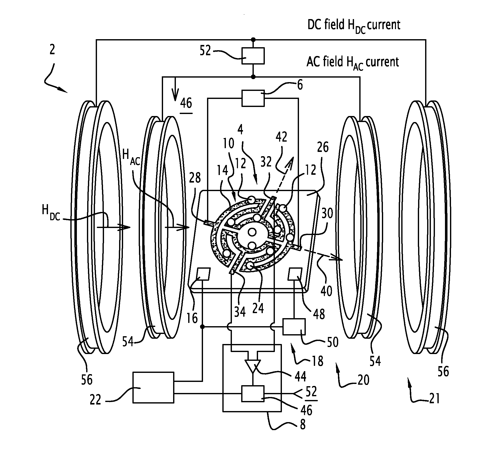
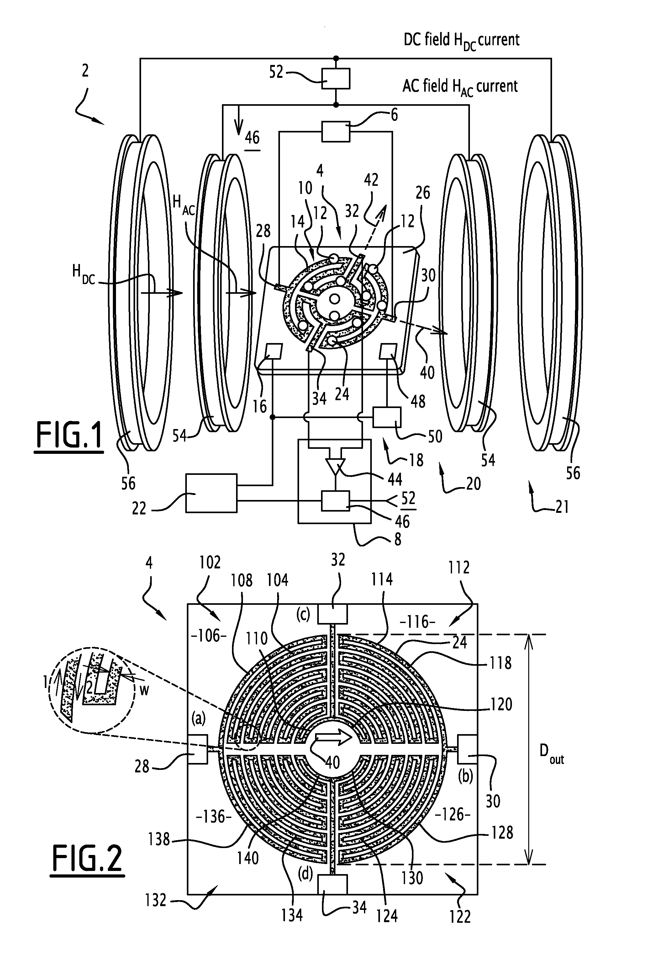
[0222]According to FIG. 6, a micromagnetometry system 302 according to the invention is derived from the micromagnetometry system 2 of FIG. 1 and comprises some parts that are designated by the same reference numerals.

[0223]The micromagnetometry system 320 of FIG. 6 differs from the micromagnetometry system of FIG. 1 in that the means 20 for creating the magnetic excitation field HAC external to the first magnetic sensor 4 are removed and replaced by the set 320 formed by the first magnetic sensor 4 and a modified first current source 326, connected between the first and second current terminals 28, 30.

[0224]In this second embodiment, the modified first current source is configured to generate an alternating current (AC) oscillating along the time at a constant frequency ω ranging from 10 to 3 KHz, here set to 100 Hz.

[0225]By self-induction, the magnetic track 24 of the first magnetic sensor 4 supplied with an alternating current (AC) by the first modified current source 326 generat...

third embodiment

[0234]According to FIG. 7, a micromagnetometry system 402 according to the invention is derived from the micromagnetometry system 2 of FIG. 1 and comprises some parts that are designated by the same reference numerals.

[0235]The micromagnetometry system 402 of FIG. 7 differs from the micromagnetometry system of FIG. 1 in that it comprises further a second hybrid AMR / PHR multi-ring magnetic sensor 404 and in that the first voltage measurement device 8 of FIG. 1 is replaced by a modified voltage measurement device 408.

[0236]The second magnetic sensor 404 has the same structure as the one of the first magnetic sensor and has closed loop magnetic track 424 with the same shape pattern.

[0237]The second magnetic sensor 404 has a first current terminal 428 and a second current terminal 430 forming a pair of current terminals which face each other contacting with the closed loop magnetic track 424.

[0238]The second magnetic sensor 404 has a first voltage terminal 432 and a second voltage termi...

first embodiment

[0251]According to FIG. 8, a micromagnetometry detection method 500 for detecting the presence of very small quantities of magnetic particles is carried out by a micromagnetometry system as defined in the FIGS. 1, 6 and 7.

[0252]This method 500 is applicable to any for magnetic particles that are switchable molecular nanoparticles by overstepping a predetermined switching threshold in terms of a switching physical property that operates as a switching command. Such magnetic particles are any switchable molecular nanoparticles in form of AhBk[M(CN)6]l.mH2O, where A can be Co, Ni, Fe, etc, B and M can be various transition metals (FeII, FeIII, MnII MnIII, fml aCoII, CoIII, . . . ) and C is an alkali metal.

[0253]The micromagnetometry detection method 500 comprises the following steps executed successively.

[0254]In a first step 502, an unknown amount of magnetic particles is deposited upon the first magnetic sensor, the magnetic particles being switchable molecular nanoparticles by overs...


PUM


Abstract

A micromagnetometry system for detecting the presence of very small quantities of magnetic particles comprises a first magnetic hybrid AMR/PHR multi-ring sensor using a Wheastone bridge electrical configuration, a first current source, a first voltage measurement device, a set of at least one magnetic particles deposited on the first magnetic sensor and a processing unit for detecting from a set of different measured differential voltages a magnetic flux shift representative of the presence of a least one deposited magnetic particle.
The micromagnetometry system comprises means for creating a magnetic excitation field HAC to make produce by each motionless magnetic particle a stray magnetic field oscillating along the time at a constant frequency ω ranging from 10 Hz to 3 KHz.

Description

FIELD OF THE INVENTION[0001]A micromagnetometry system for detecting the presence of very small quantities of magnetic particles.BACKGROUND OF THE INVENTION[0002]Nowadays nano-sized Spin CrossOver (SCO) particles receive more and more interests not only for the exploration of the physical properties of these materials at the mesoscopic scale, but also for the development of new functional materials. Up to now observations of the spin transition property was essentially reduced to the simple investigation of temperature dependence of the magnetization or the optical absorption in a huge ensemble of nano-particles with different degrees of size and shape dispersion. The development of methods for single Spin CrossOver (SCO) particle measurements is desirable for both fundamental and applicative perspective even if such efforts remain scare so far.[0003]In the field of nano-scale magnetic measurements, the state of the art is represented by the micro-SQUID and nano-SQUID devices. These...

Claims


Application Information

Patent Timeline
IPC IPC(8): G01R33/07G01R33/09
CPCG01R33/072G01R33/096G01R33/091G01R33/1269G01N27/745B82Y25/00
Inventor TERKI, FERIALBOUSSEKSOU, AZZEDINETRAN, QUANG HUNGKAMARA, SOULEYMANKIM, CHEOLGIKIM, KUN WOOGANDIT, PHILIPPE
Owner UNIV DE MONTPELLIER
Why Eureka
Try Eureka