Presbyopia correcting wireless optical system

a wireless optical system and presbyopia technology, applied in the field of presbyopia correction wireless optical system, can solve the problems of additional uncertainty between individual differences, inability to accurately detect the individual differences, so as to reduce the processing power and reduce power consumption.

Active Publication Date: 2015-06-25
PORTNEY VALDEMAR
View PDF13 Cites 20 Cited by
  • Summary
  • Abstract
  • Description
  • Claims
  • Application Information

AI Technical Summary

Benefits of technology

[0035]The present invention also discloses dual-chamber electrostatically activating fluidic lens as a desirable option for a wireless system that includes a sensor cell that responds to ciliary muscles contraction and relaxation for the signal transmission to the adjustable lens. There is also an advantage to apply specific type two-chamber fluidic switchable lens that was disclosed in the U.S. Patent Application 2014 / 0085726 entitled “Refractive Diffractive Switchable Optical Element”. This type of adjustable lens acts as opto-mechanical transistor where the optical powers for far and near foci are set by the lens design itself. The corresponding optic is called RDS optic and it allows a reduction of necessary processing power because it is inherently digital by design due to switching between preset far and near foci if a signal is below set threshold or above it. It also reduced power consumption as the power is used only to change to preexisting optical power state of the RDS optic without a need to continually control the optical power state of the lens.

Problems solved by technology

Thus, NFC-enabled device allows automatic “pairing” and effortless communication and control of data transfer.
An inclusion of electromagnet is fairly complex and involves a current flow to create a magnetic field which is an additional safety issue.
This is additional uncertainty between the individual differences with signal characteristics which has not been addressed.
Another complexity is the use of micromotor to compress the lens for optical power change.
The publication described a number of difficulties for continuous communication without providing descriptions how to reduce the described concepts to practice.
The ciliary muscles mechanics is a complex system and it would be desirable to achieve a continuous focus from far to near but such a system presents the immense difficulty which has not been addressed by the application.
Though a wireless communication has been used before, its proper and practical application to a biological system and particularly to presbyopia correction is lacking.
Another deficiency is the absence of systemic approach, the disclosures either describe a communication between a sensor and a lens in general terms without a specific explanation how the communication is reduced to the actual presbyopia correction or an implementation of the sensor is rather questionable in terms of its position inside the eye.
There are multiple issues which have not been addressed by prior arts: (1) ciliary muscles structure is complex and depending upon sensor cell location, the signal detecting their actions can vary significantly; (2) some disclosures mentioned signal calibration without explaining what it actually is; (3) even if a calibration of some sort is performed, it must be done with an adjustable lens in place leading to another complication that the surrounding of the lens is also not fixed as any biological system potentially leading to re-calibration; (4) adjustable lenses are likely implanted binocularly and calibration of the sensor for one lens might not be applicable for another lens unless two sensor cells are installed individually for each lens which is highly undesirable.
On the other hand, if adjustable lenses have to be calibrated, it would evolve more complex structure and cost of the adjustable lenses.

Method used


Image

  • Presbyopia correcting wireless optical system
  • Presbyopia correcting wireless optical system
  • Presbyopia correcting wireless optical system

Examples


Embodiment Construction

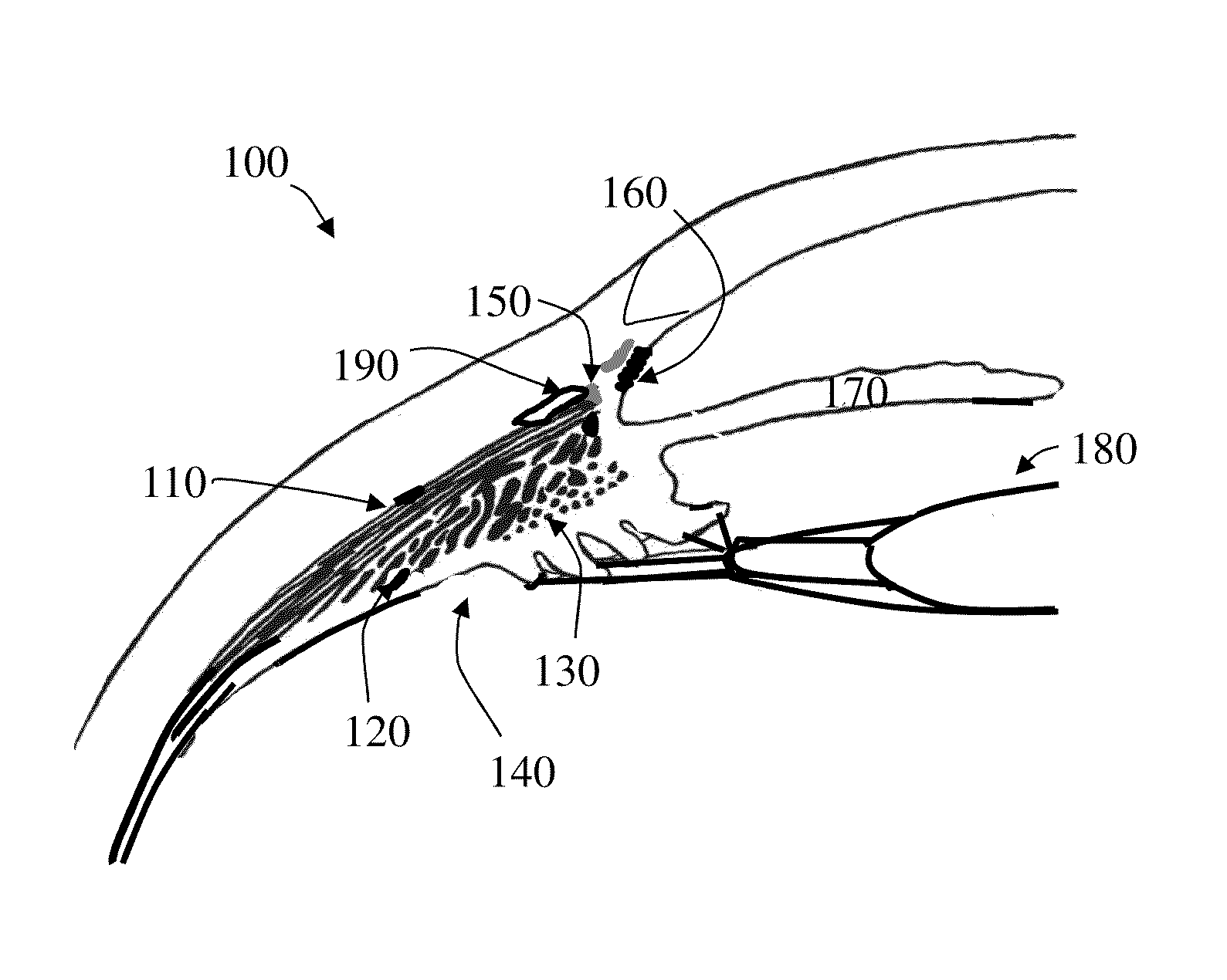
[0053]FIG. 1 illustrates a portion 100 of eye anatomy responsible for the accommodation process shown as the eye's cross section. The FIG. 1 includes implanted aphakic intra-ocular lens 180 that replaces natural lens. The ciliary muscles accommodating apparatus is confined by ciliary body 140 and is divided into longitudinal fibers 110, radial fibers 120 and circular fibers 130 each having different orientation and, as a result, contracting in different planes. At the front, the longitudinal fibers 110 attach to the scleral spur 150, whereas the radial 120 and circular fibers 130 attach to the back of the trabecular meshwork 160 and posterior wall of the iris 170. Radial fibers 120 are composed of few thin fibers that contracts during disaccommodation (from near to far focus) to focus far objects by pulling out the equatorial part of the eye's capsular bag of the natural lens. Most of circular fibers 130 run in a circle around the ciliary body 140 concentrically with the root of iri...


PUM


Abstract

An optical accommodating system for an eye includes a sensor assembly and an adjustable optic assembly. The sensor assembly includes a sensor configured to sense a movement of the ciliary muscle and produce a signal, an electronic processor, a transmitter and a power source. The adjustable optic assembly is configured to be either implanted within or on the eye, or configured to be disposed adjacent to or near the eye. The adjustable optic assembly includes a switchable optical lens assembly configured to change its optical power between a first state and a second state, a receiver configured to receive the transferable signal from the transmitter of the sensor assembly, a second electronic processor connected to the receiver which directs the switchable optical lens assembly to change its optical power between the first state and second state, and a second power source connected to the second electronic processor.

Description

CROSS-REFERENCE TO RELATED APPLICATIONS[0001]The present application is a continuation-in-part of application Ser. No. 14 / 082,039 filed on Nov. 15, 2013, which was a divisional application of application Ser. No. 13 / 247,840 filed Sep. 28, 2011 now U.S. Pat. No. 8,608,800 issued on Dec. 17, 2013, which itself claimed priority from provisional application 61 / 514,413 filed Aug. 2, 2011. The present application also claims priority to provisional patent application 61 / 950,942 filed on Mar. 11, 2014, provisional application 61 / 984,954 filed on Apr. 28, 2014 and provisional application 62 / 027,123 filed on Jul. 21, 2014. The entire contents of all the applications mentioned herein are hereby incorporated by reference in their entirety.DESCRIPTION[0002]1. Field of the Invention[0003]The present invention relates generally to a sensor interacting with ciliary muscles that transmits a signal to an ophthalmic lens to change its optical power between far and near foci. More particularly, the pr...

Claims


Application Information

Patent Timeline
Patent Type & Authority Applications(United States)
IPC IPC(8): A61F2/16G02C7/08A61F2/14
CPCA61F2/1654A61F2/142A61F2250/0004G02C7/085A61F2/1635G02C7/04G02C2202/20A61F2/145A61F2250/0002A61F2/482
Inventor PORTNEY, VALDEMAR
Owner PORTNEY VALDEMAR
Why Eureka
Try Eureka