Method for wire saw excavation

a wire saw and excavation method technology, applied in the direction of metal sawing apparatus, cutting machines, dislodging machines, etc., can solve the problems of destroying the core material being removed, affecting the excavation effect, so as to reduce the time, effort and expense.

Inactive Publication Date: 2015-06-25
KING FAHD UNIVERSITY OF PETROLEUM AND MINERALS
View PDF0 Cites 5 Cited by
  • Summary
  • Abstract
  • Description
  • Claims
  • Application Information

AI Technical Summary

Benefits of technology

[0008]The method for wire saw excavation greatly reduces the time, effort, and expense of conventional wire saw excavation methods and procedures by requiring the drilling or forming of only a single downhole in the substrate. The shape of the desired excavation is initially determined on the face of the substrate (e.g., rock, concrete, etc.) to be cut, and the single downhole or guide hole is formed at some point along the periphery of the shape or mass to be cut from the substrate. The downhole may be formed by conventional boring or drilling, or by means of a micro-excavator. Such a micro-excavator may be a reduced scale version of larger tunnel boring machines, rock drills, and the like, capable of forming a hole having a diameter on the order of only four to ten inches (ten to twenty-five centimeters).
[0011]The first method uses two robotic guide pulleys positioned at the bottom of the downhole to travel in opposite directions through the base passage. The wire saw passes around these two robotic pulleys, and cuts in a plane across the base passage as the two robotic pulleys advance in opposite directions along the base passage. Alternatively, one pulley may be stationary while the other pulley travels along the base passage. The wire saw does not extend up the downhole during this portion of the cutting process using this method, and no cutting of the peripheral shape of the core is accomplished at this point. Once the bottom cut has been accomplished as described immediately above, the wire saw is positioned about a surface pulley and a subsurface pulley at the bottom of the downhole. The two pulleys are advanced along the predetermined path for the peripheral cut in order to complete the cut. Alternatively, two surface pulleys and two subsurface pulleys may be used to cut in opposite directions along the predetermined path, thereby accelerating the cutting process.
[0013]When the cuts have been completed, the core is unattached to any of the structure of the substrate. At this point, the two subsurface pulleys are removed through the single downhole and a mechanism is sent down the hole to push the core from the completed hole. A traction device may be attached to the face of the cut core in lieu of or in addition to the pusher device, if desired. The moving of the core at least slightly outward from the substrate provides some working room behind the core to allow guide pulleys to be positioned in this volume behind the core. This allows the core to be sectioned into multiple pieces to facilitate removal. The core sectioning process is accomplished in much the same manner as that described further above for cutting the core from the substrate.

Problems solved by technology

However, explosives can be difficult to control accurately, and not only destroy the core material being removed, but may also fracture and weaken the surrounding substrate.
This requires considerably more time, effort, and cost to reinforce the weakened substrate around the hole formed by the detonated explosive charge.
While mechanized equipment does not generally cause so much damage to the surrounding substrate, it generally results in the destruction of the core material.
The need for the formation of multiple downholes in the substrate requires significantly more time and effort than would otherwise be required if only a single downhole were needed.

Method used


Image

  • Method for wire saw excavation
  • Method for wire saw excavation
  • Method for wire saw excavation

Examples


Embodiment Construction

[0030]The method for wire saw excavation according to the present invention requires only a single downhole to be drilled or otherwise formed into the substrate from which a core of material is to be cut and removed. The requirement for only a single downhole greatly reduces the time, effort, and cost involved in the extraction of a core of material from a hard substrate, such as solid rock or concrete. Moreover, the resulting solid core may be extracted in blocks or other forms having economic value. For example, when marble material is cut, the core may be removed as a solid marble block and used to form building material, for sculpture, etc.

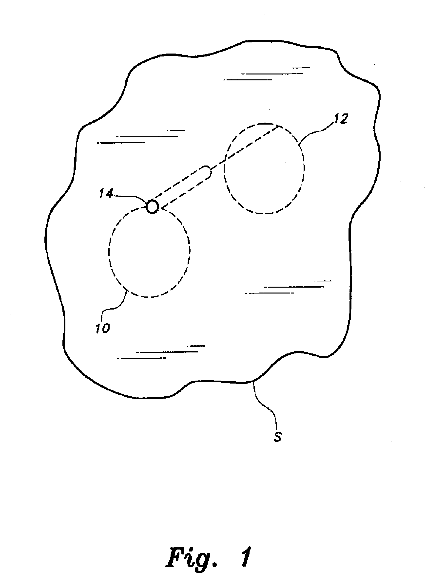
[0031]FIG. 1 of the drawings provides a schematic perspective view of a planned core cut and extraction from a substrate S. The initial step in the core cutting and extraction method is illustrated in FIG. 1, i.e., the shape of the periphery of the core to be cut has been indicated both on the face of the substrate (as indicated by the dashed ...


PUM

PropertyMeasurementUnit
diameteraaaaaaaaaa
diameteraaaaaaaaaa
depthaaaaaaaaaa

Abstract

The method for wire saw excavation provides a significant savings in time, effort, and expense in the cutting of a core of material from a solid substrate such as rock or concrete. A single downhole is formed, and a robotic excavator then forms a continuous, closed loop base passage at the distal end of the downhole to define the periphery of the core to be cut. When the base passage has been completed, the robotic excavator is removed and two subsurface guide pulleys are placed in the bottom of the downhole. A wire saw is passed from a first surface pulley around the first and second subsurface pulleys and back to a second surface pulley. The surface pulleys are advanced along the predetermined periphery of the core at the same rate as the subsurface pulleys, so that the saw simultaneously cuts the periphery and the bottom of the core.

Description

CROSS REFERENCE TO RELATED PATENT APPLICATION[0001]This application is a continuation-in-part of U.S. patent application Ser. No. 14 / 104,387, filed on Dec. 12, 2013.BACKGROUND OF THE INVENTION[0002]1. Field of the Invention[0003]The present invention relates generally to the excavation of solid substrates, and particularly to a method for wire saw excavation wherein a single downhole is formed into the substrate and a wire saw is used to cut a core from the substrate from the single downhole.[0004]2. Description of the Related Art[0005]A number of different methods have been developed in the past for earth excavation and tunneling. While the earliest tunnels and excavations were carried out using hand tools, a more practicable approach is by means of mechanized tools and equipment and / or the use of explosives. However, explosives can be difficult to control accurately, and not only destroy the core material being removed, but may also fracture and weaken the surrounding substrate. T...

Claims


Application Information

Patent Timeline
Patent Type & Authority Applications(United States)
IPC IPC(8): B28D1/08E21D1/06E21D9/10E21C25/54
CPCB23D57/0007E21C25/56E21D9/1053E21C25/54E21D1/06B28D1/088E21B7/068
Inventor ALSADAH, JIHAD HASSANMOGAHED, ELSAYED AHAMAD
Owner KING FAHD UNIVERSITY OF PETROLEUM AND MINERALS
Why Eureka
Try Eureka