Pressure control valve including a compensating chamber

Active Publication Date: 2015-06-25
ROBERT BOSCH GMBH
View PDF23 Cites 7 Cited by
  • Summary
  • Abstract
  • Description
  • Claims
  • Application Information

AI Technical Summary

Benefits of technology

The present invention provides a pressure control valve with a housing and a control piston actuated by an armature in a magnet chamber of a pole tube. A compensating channel is hydraulically connected to the magnet chamber and the housing, which is delimited by a solenoid coil and the housing. The compensating channel allows for settling of particles and prevents ferromagnetic particles from adhering in the housing. The valve has a slide configuration that prevents dirt particles from affecting its function. The valve is ventilated through an opening in the outer housing side, ensuring a largely undamped movement of the control piston and armature. The compensating channel is a radial transverse bore in the pole tube, which is simple to manufacture and ensures a ventilating function of the magnet chamber. The cross section of the compensating channel should not be too large or too small to maintain its function.

Problems solved by technology

Consequently, oil is displaced by the movement of the control piston or, in turn, oil is drawn in due to a resulting vacuum.
In the hydraulic oil reservoir, such ferromagnetic particles and other dirt particles may lead to functional impairments or malfunctions.
Thus, for example, the guidance of the control piston or the electromagnetic actuation of the control piston may be adversely affected due to the contaminants.

Method used


Image

  • Pressure control valve including a compensating chamber
  • Pressure control valve including a compensating chamber
  • Pressure control valve including a compensating chamber

Examples


Embodiment Construction

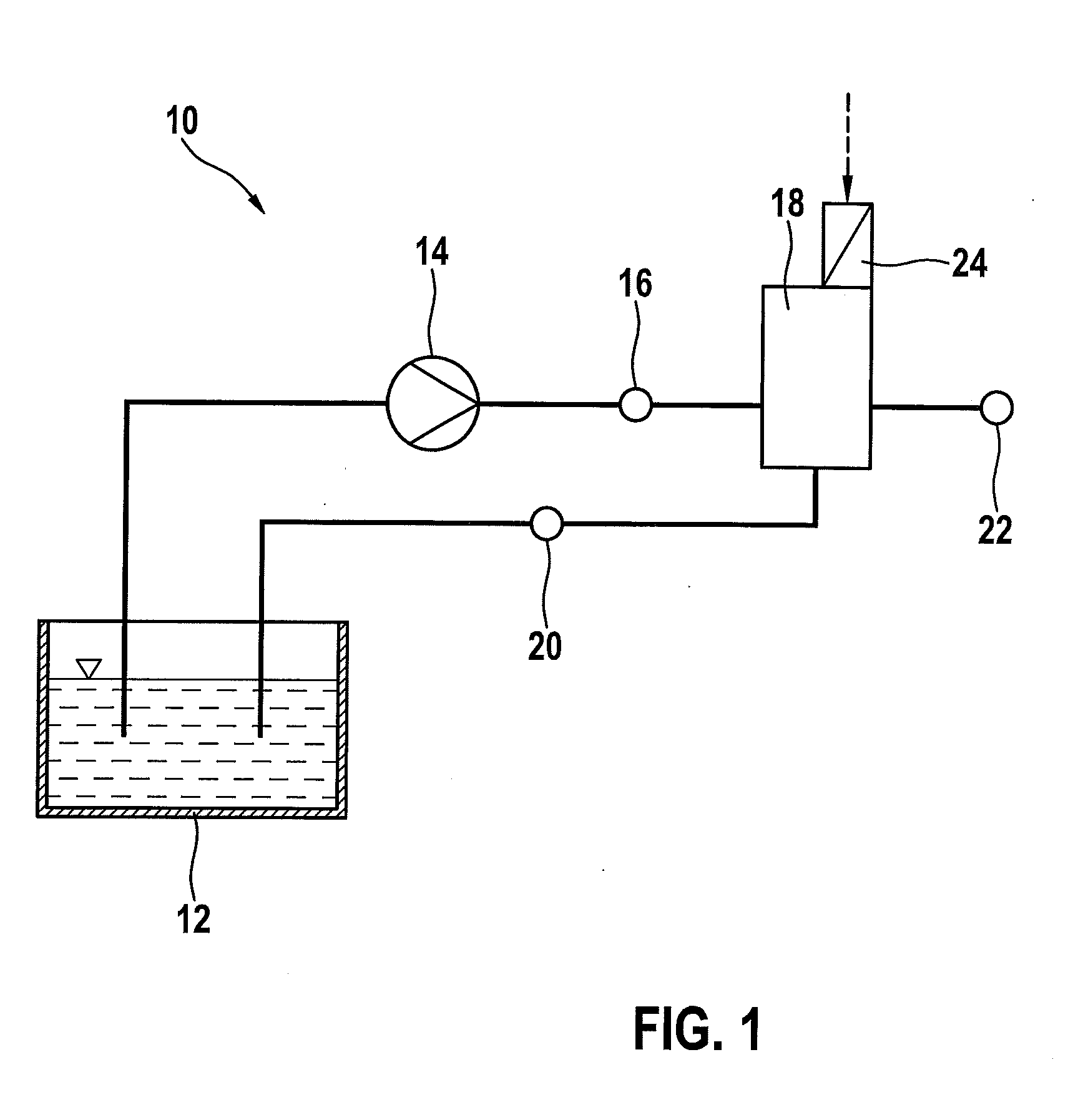
[0023]To control automatic transmissions, as they are used, for example, in passenger cars, a hydraulic circuit 10, among other things, is used, of which a pressureless hydraulic oil reservoir 12 and a hydraulic pump 14 are a part. An outlet of the hydraulic pump 14 forms a supply connection 16, to which a pressure control valve 18 is connected.

[0024]A return flow from pressure control valve 18 leads to a return flow connection 20, which leads back to hydraulic reservoir 12. Pressure control valve 18 is also connected to a working connection 22, at which the pressure to be controlled by pressure control valve 18 is present. In addition, pressure control valve 18 includes an electromagnetic actuation device 24.

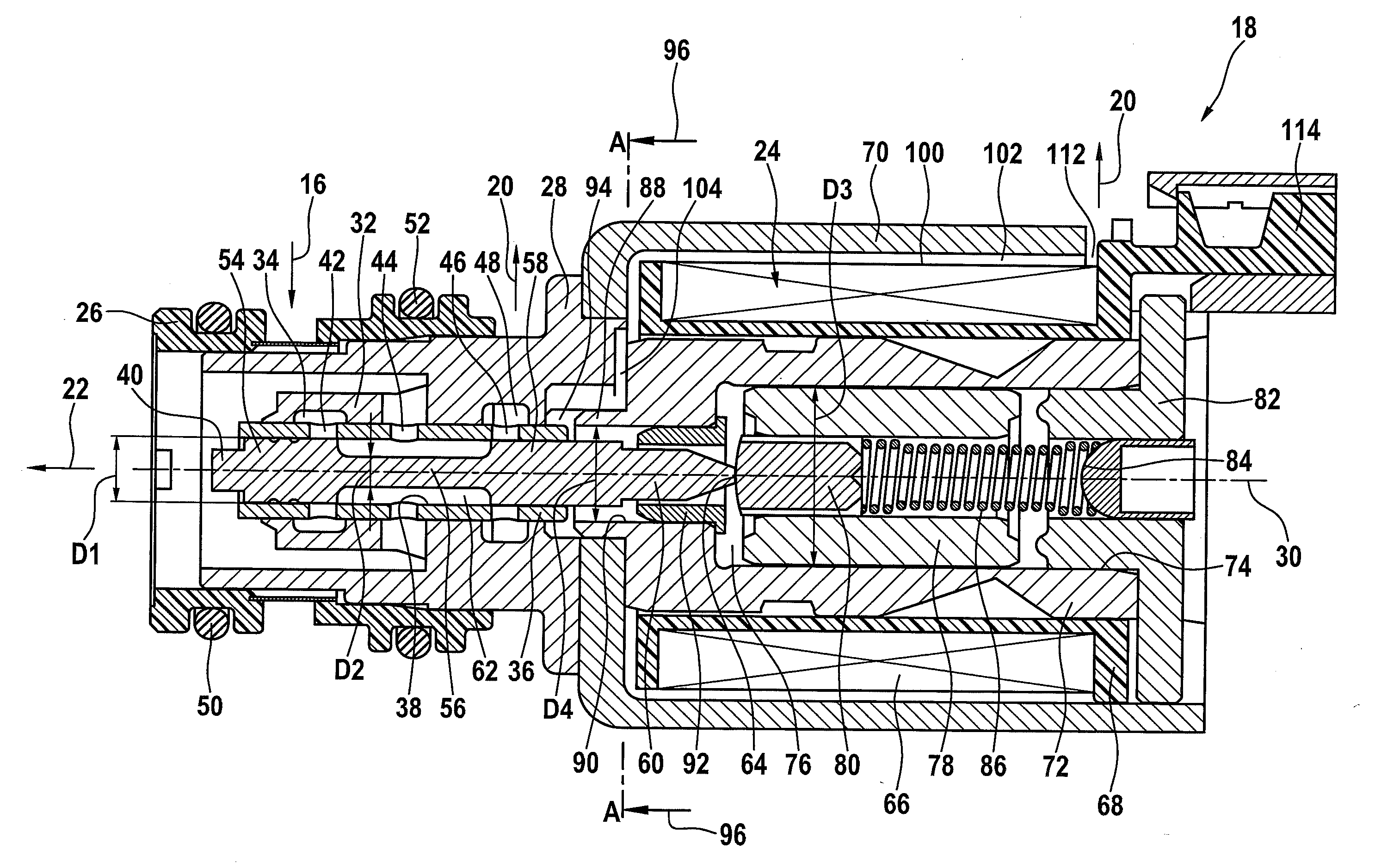
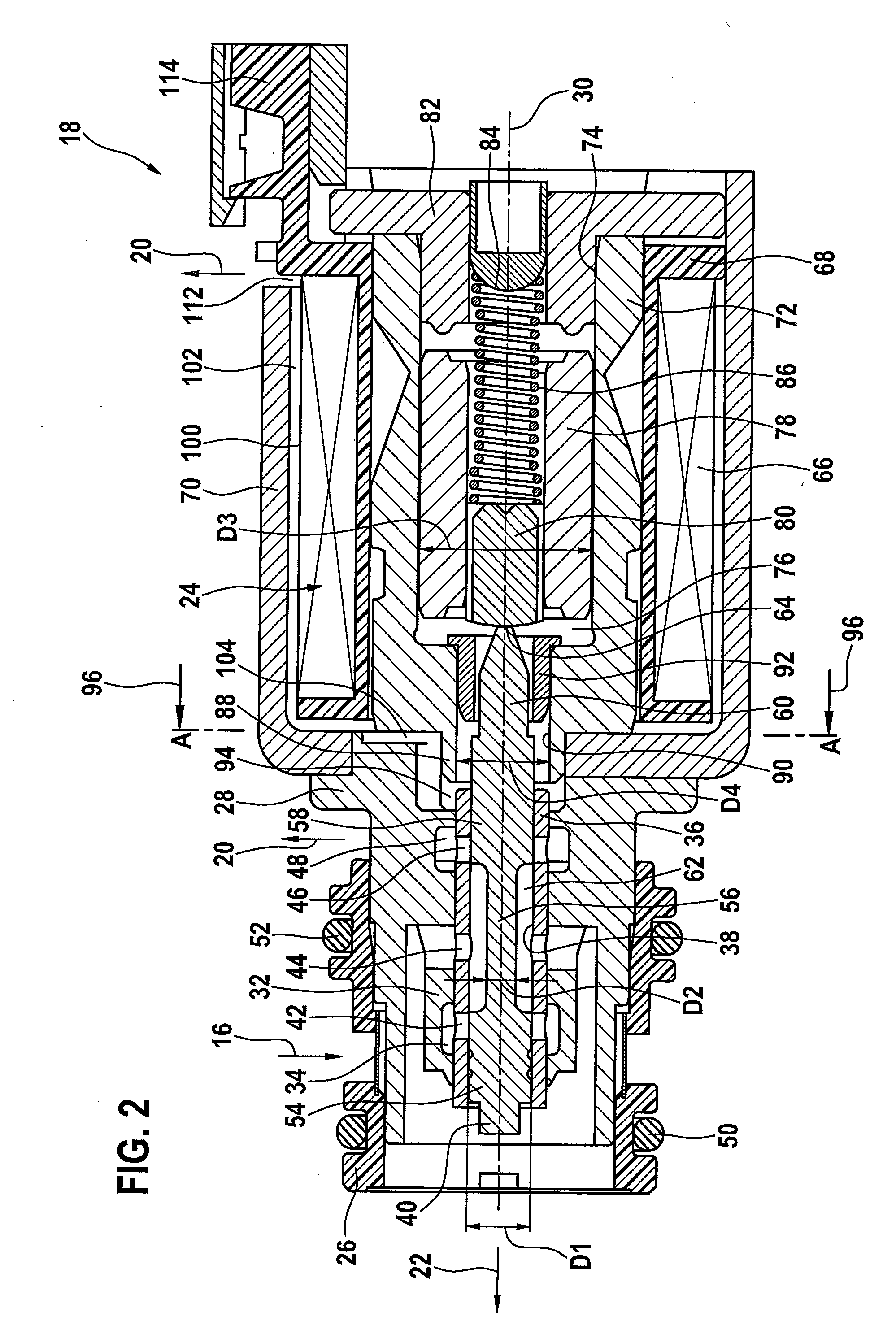
[0025]FIG. 2 depicts the structure of a pressure control valve 18 according to the present invention. Pressure control valve 18 includes a valve connection element 26, which is slid on to a hydraulic housing 28 and is sealingly connected to hydraulic housing 28. Valve connectio...


PUM


Abstract

A pressure control valve, in particular for an automatic transmission in a motor vehicle, including a housing and including a control piston situated in the housing, the control piston being actuatable by an armature situated in a magnet chamber of a pole tube, the magnet chamber being hydraulically connected to a compensating chamber provided in the housing, which is delimited, in particular by a lateral surface of a solenoid coil and the housing.

Description

RELATED APPLICATION INFORMATION[0001]The present application claims priority to and the benefit of German patent application No. 10 2013 226 615.4, which was filed in Germany on Dec. 19, 2013, the disclosure of which is incorporated herein by reference.FIELD OF THE INVENTION[0002]The present invention relates to a pressure control valve, in particular for an automatic transmission in a motor vehicle.BACKGROUND INFORMATION[0003]In modern automobile automatic transmissions, hydraulically actuated clutches are used to change gears. In order for these shift operations to occur smoothly and unnoticed by the driver, it is necessary to adjust the hydraulic pressure on the clutches according to predefined pressure ramps with the maximum possible pressure precision. For this purpose, electromagnetically actuated pressure control valves are used. These may be configured as either seat valves or slide valves. Both configurations normally include three hydraulic connections, for intake, control...

Claims


Application Information

Patent Timeline
IPC IPC(8): F16H61/02F16H61/06
CPCF16H61/065F16H61/0206F16H61/0251F16K31/0613F16H2061/0258Y10T137/86622
Inventor SCHUDT, KLAUSMUELLER, ERWIN
Owner ROBERT BOSCH GMBH
Why Eureka
Try Eureka