Lighting device and method for providing light

Inactive Publication Date: 2015-06-25
SHARP KK
View PDF9 Cites 10 Cited by
  • Summary
  • Abstract
  • Description
  • Claims
  • Application Information

AI Technical Summary

Benefits of technology

[0030]According to one aspect of the invention, a lighting device includes: a transparent optical cavity including an exit surface including a specularly reflective material arranged to reflect light into the cavity, the exit surface having a plurality of apertures formed therein, a base surface including a specularly reflective material arranged to reflect light into the cavity, and at least one light receiving surface arranged relative t

Problems solved by technology

In general out-coupling light from lightguides and reflection from diffuse reflectors is not a good way of providing precise control over the angular properties of emitted light from a lightguide or luminaire; approximate

Method used


Image

  • Lighting device and method for providing light
  • Lighting device and method for providing light
  • Lighting device and method for providing light

Examples


Embodiment Construction

[0070]A lighting device in accordance with the present invention includes a transparent optical cavity having an exit surface, a base surface and a light receiving surface formed in or relative to the base surface. The exit surface and the base surface include a specularly reflective material, and a plurality of apertures are formed in the exit surface, wherein the apertures are arranged to maximize at least one of uniformity, angular distribution, efficiency or luminous intensity of light exiting the exit surface. Further, at least one of a combination of the exit surface and base surface, or the light receiving surface alters a distribution of light received at the light receiving surface.

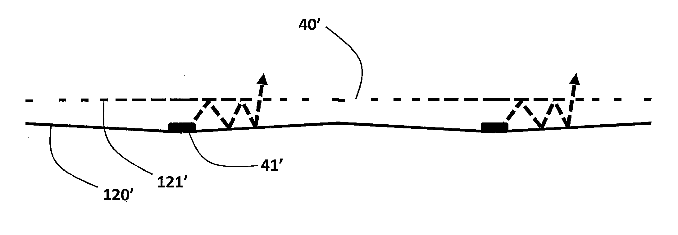
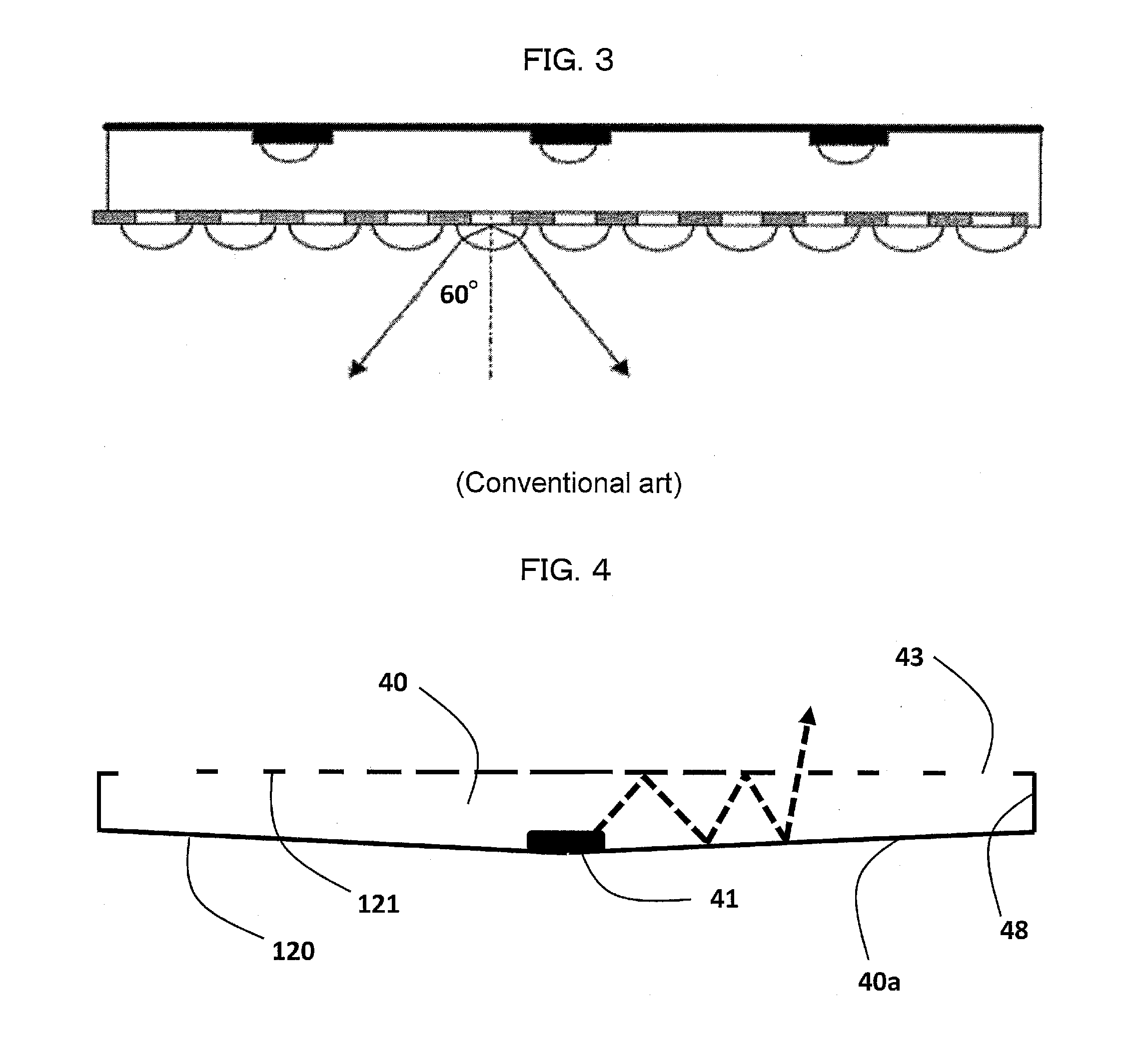
[0071]FIG. 4 shows a preferred embodiment in accordance with the present invention. A light source, 41, is used and this is referred to in subsequent discussions as an LED, but the invention is not limited to this type of light source.

[0072]The optic consists of a cavity, 40, which can be air fil...


PUM


Abstract

A lighting device includes a transparent optical cavity having an exit surface including a specularly reflective material arranged to reflect light into the cavity, the exit surface having a plurality of apertures formed therein, a base surface including a specularly reflective material arranged to reflect light into the cavity, and at least one light receiving surface arranged relative to the base surface and configured to receive light from a light source. The plurality of apertures are arranged to maximize at least one of uniformity, angular distribution, efficiency or luminous intensity of light exiting the exit surface, and a distribution of light received at the light receiving surface is altered by at least one of a combination of the exit surface and the base surface, or the light receiving surface.

Description

TECHNICAL FIELD[0001]This invention relates to a directional luminaire (for example a spot or accent light) capable of providing light in an indoor or outdoor environment. It further refers to spotlights that can have a thin profile and to those that require reduced glare. This luminaire has the further capability of providing angle and direction-controlled illumination.BACKGROUND ART[0002]This application claims priority of U.S. Provisional Application No. 61 / 673,902 filed on Jul. 20, 2012 and U.S. application Ser. No. 13 / 563,117 filed on Jul. 31, 2012, which are incorporated herein by reference in its entirety.[0003]Directional luminaires such as spotlights, accent lights, downlighters, etc. are used in a wide variety of applications in residential, commercial and industrial premises. They are used particularly where a high surface brightness is required such as task lighting in kitchens and in retail accent lighting. These luminaires, at the basic level, consist of two components...

Claims


Application Information

Patent Timeline
IPC IPC(8): F21V13/14F21K99/00
CPCF21V13/14F21W2131/40F21Y2101/02F21K9/1375F21V7/0025F21V11/14F21V13/04F21Y2105/00F21Y2115/10F21V7/24G02B6/0046G02B6/0055G02B6/0096G02B6/00
Inventor MITCHELL, SARAH ANNEMONTGOMERY, DAVID JAMESROBERTS, PETER JOHNHEFFERNAN, JONATHANSUCKLING, JAMES ROWLANDRIHANI, SAMIR
Owner SHARP KK
Why Eureka
Try Eureka