Zero Standby Power for Powerline Communication Devices

Active Publication Date: 2015-06-25
STMICROELECTRONICS INT NV
View PDF2 Cites 6 Cited by
  • Summary
  • Abstract
  • Description
  • Claims
  • Application Information

AI Technical Summary

Benefits of technology

The patent describes an integrated system on chip (SoC) that includes a communication interface that can minimize power consumption by selectively activating or deactivating certain functional blocks. The system also includes a receiver identification (ID) detection function to determine if the received signal is intended for the device in which the SoC resides. The SoC's power management function controls which functions are activated or deactivated based on the results of the receiver ID detection function. The system also includes a power source that can activate only the necessary functional blocks for signal receipt and detection in a low power state and switch over to the main power supply when the SoC is activated. The patent also describes a method for receiving a message from a network, detecting the destination address of the message, and selectively activating the necessary functional blocks based on the destination address. The technical effects of the patent include optimized power consumption and efficient signal processing.

Problems solved by technology

As is generally known, an electrically powered device in standby mode is in any case supplied power through a main power-supply, such as domestic power, and consumes energy.
However, it is evident that, if the consumption in standby mode of a plurality of electrically powered devices generally present in dwellings is considered, non-negligible daily consumption levels may be reached.

Method used


Image

  • Zero Standby Power for Powerline Communication Devices
  • Zero Standby Power for Powerline Communication Devices
  • Zero Standby Power for Powerline Communication Devices

Examples


Embodiment Construction

[0011]The making and using of embodiments are discussed in detail below. It should be appreciated, however, that the present disclosure provides many applicable inventive concepts that may be embodied in a wide variety of specific contexts. The specific embodiments discussed are merely illustrative of specific ways to make and use the invention, and do not limit the scope of the invention.

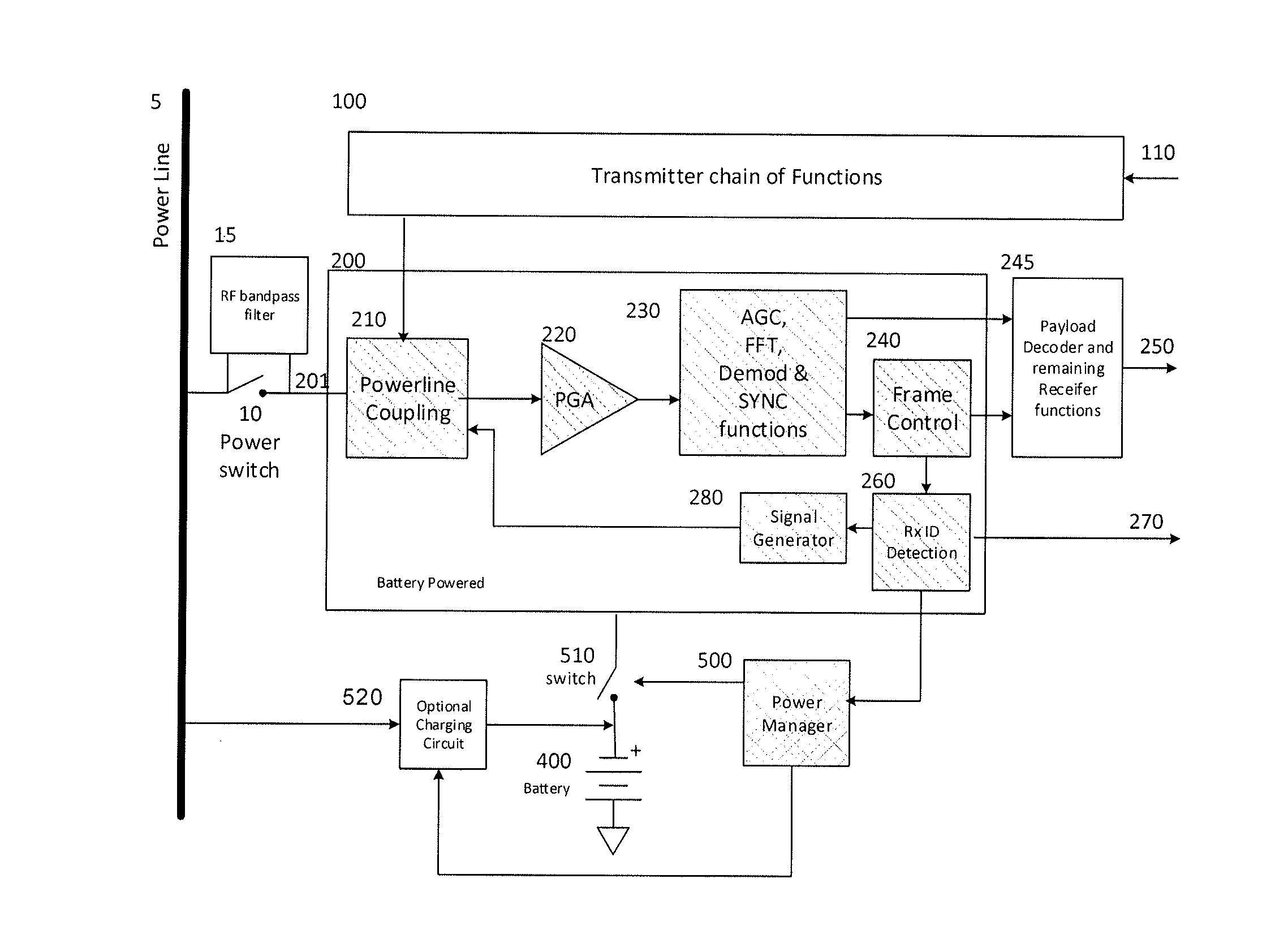
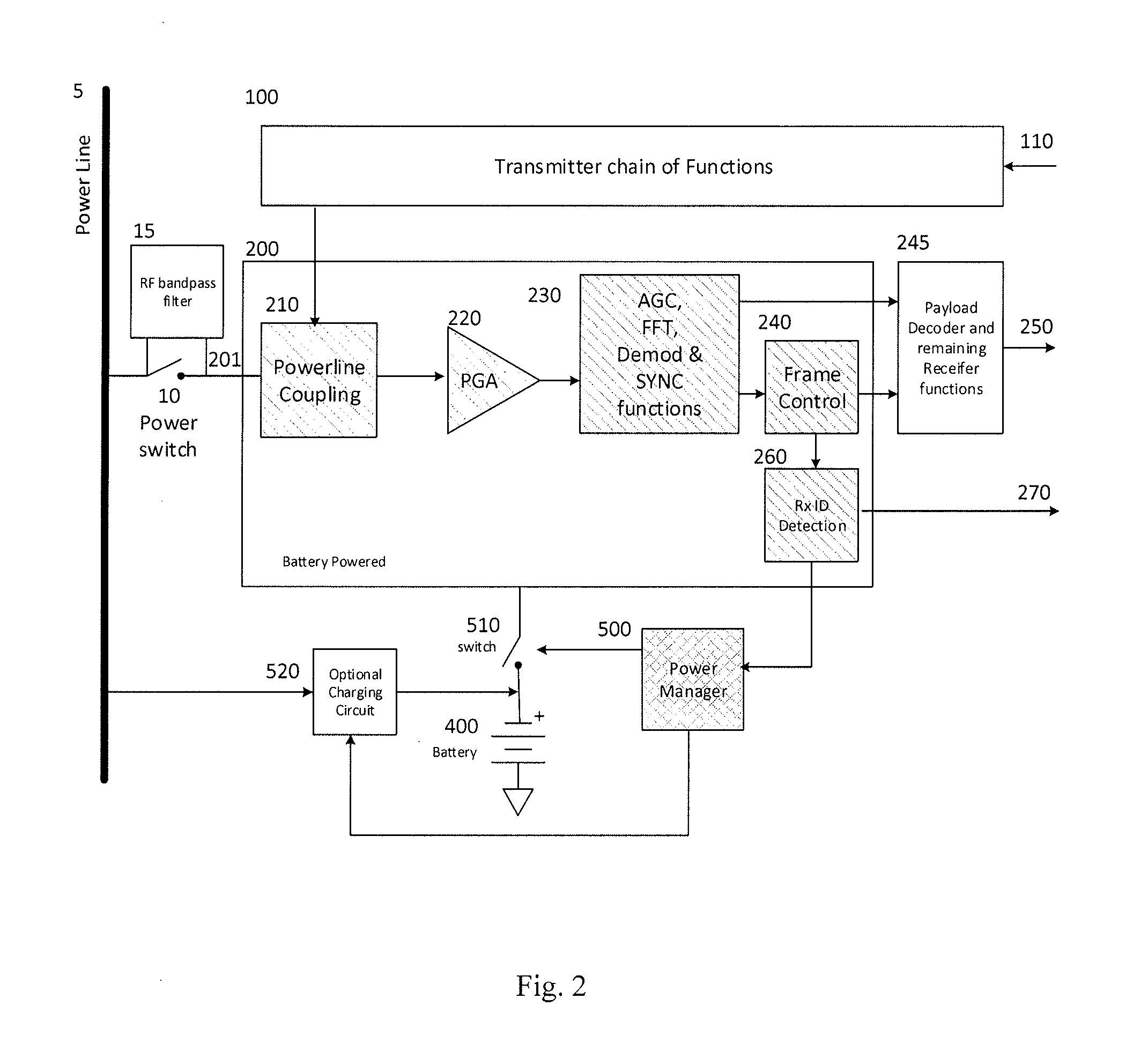
[0012]The present disclosure will be described with respect to embodiments in a specific context, namely a method and apparatus for improving the standby power consumption of network connected systems. Embodiments of this invention may also be applied to other circuits and systems, such as, but not limited to, wireless systems such as wireless communication systems.

[0013]Some attempts at reducing the energy consumed by electrically powered devices in a standby mode are to use a remote control as a stimulus to trigger a mechanism that powers on the system. Some examples of these types of systems are...


PUM


Abstract

An embodiment is an integrated System on Chip (SoC) including a communication interface configured to implement a communication protocol including functional blocks that are energized or de-energized individually so that a minimum power consumption is used to receive and detect a signal, and a receiver identification (ID) detection function configured to determine whether the signal is intended for the device in which the SoC resides. The SoC further includes a power management function configured to control which functions in the SoC and / or device in which the SoC resides are energized or de-energized depending on the results of the receiver ID detection function, and a power source capable of energizing a minimum number of the functional blocks required to receive and detect a signal, wherein the power source can be used in a low power state and switched over to a main power supply when the SoC is energized.

Description

PRIORITY CLAIM AND CROSS-REFERENCE[0001]This application claims the benefit of the following provisionally filed U.S. patent application: Application Ser. No. 61 / 918,366, filed Dec. 19, 2013, and titled “Zero Standby Power for Powerline Communication Devices,” which application is hereby incorporated by reference.TECHNICAL FIELD[0002]The present disclosure relates generally to the device architecture for devices that communicate over local area communications networks and, more specifically, to a powerline communications (PLC) network interface.BACKGROUND[0003]It is well known in the art that it is important to reduce the energy consumed by electrically powered devices, especially while they are not being used (e.g., in “standby”, “idle”, and / or “fast-wake” modes). In this mode, the electrically powered device is inactive as regards normal operation (e.g., display of images for a television set, sound reproduction for hi-fi equipment, etc.). As is generally known, an electrically po...

Claims


Application Information

Patent Timeline
IPC IPC(8): H04B3/54H04L12/28H04L12/10
CPCH04B3/542H04L2012/2843H04L12/2838H04L12/10G06F1/3209G06F1/3287Y02D10/00
Inventor LOGVINOV, OLEG
Owner STMICROELECTRONICS INT NV
Why Eureka
Try Eureka