Control Scheme for Hysteretic Buck Controller with Inductor Coil Current Estimation

Active Publication Date: 2016-10-20
DIALOG SEMICON UK
View PDF15 Cites 20 Cited by
  • Summary
  • Abstract
  • Description
  • Claims
  • Application Information

AI Technical Summary

Benefits of technology

The patent aims to find a solution that doesn't increase the noise caused by the circuitry used to sense electric current.

Problems solved by technology

The disadvantage of this prior art embodiment is the high quiescent current due to dual current sensing circuit which causes lower efficiency at light loads.
In addition, a second disadvantage is the current sensing circuitry are usually noisy and layout sensitive.
Additionally, another disadvantage is that the current sensing circuitry can also introduce switching noise.

Method used


Image

  • Control Scheme for Hysteretic Buck Controller with Inductor Coil Current Estimation
  • Control Scheme for Hysteretic Buck Controller with Inductor Coil Current Estimation
  • Control Scheme for Hysteretic Buck Controller with Inductor Coil Current Estimation

Examples


Embodiment Construction

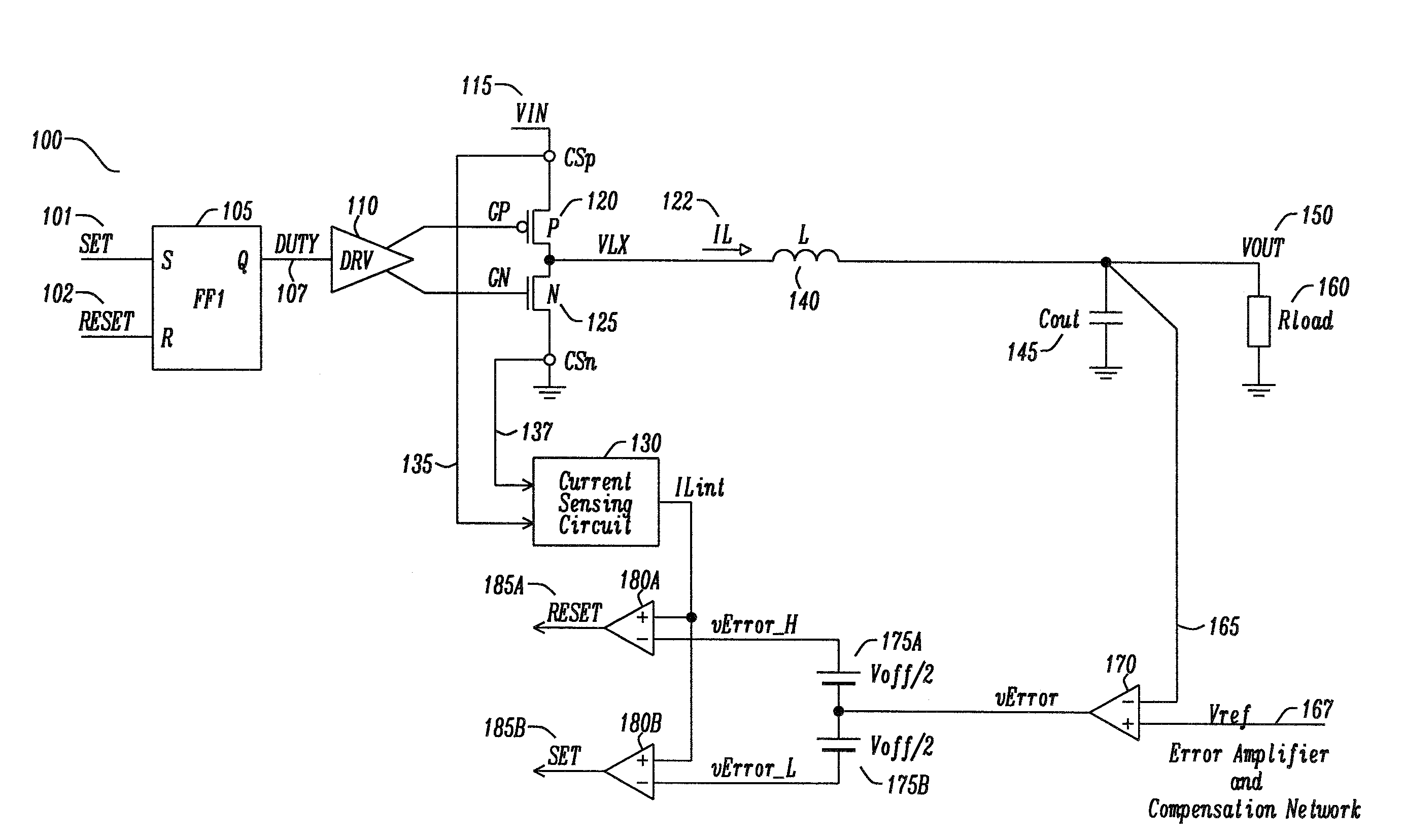
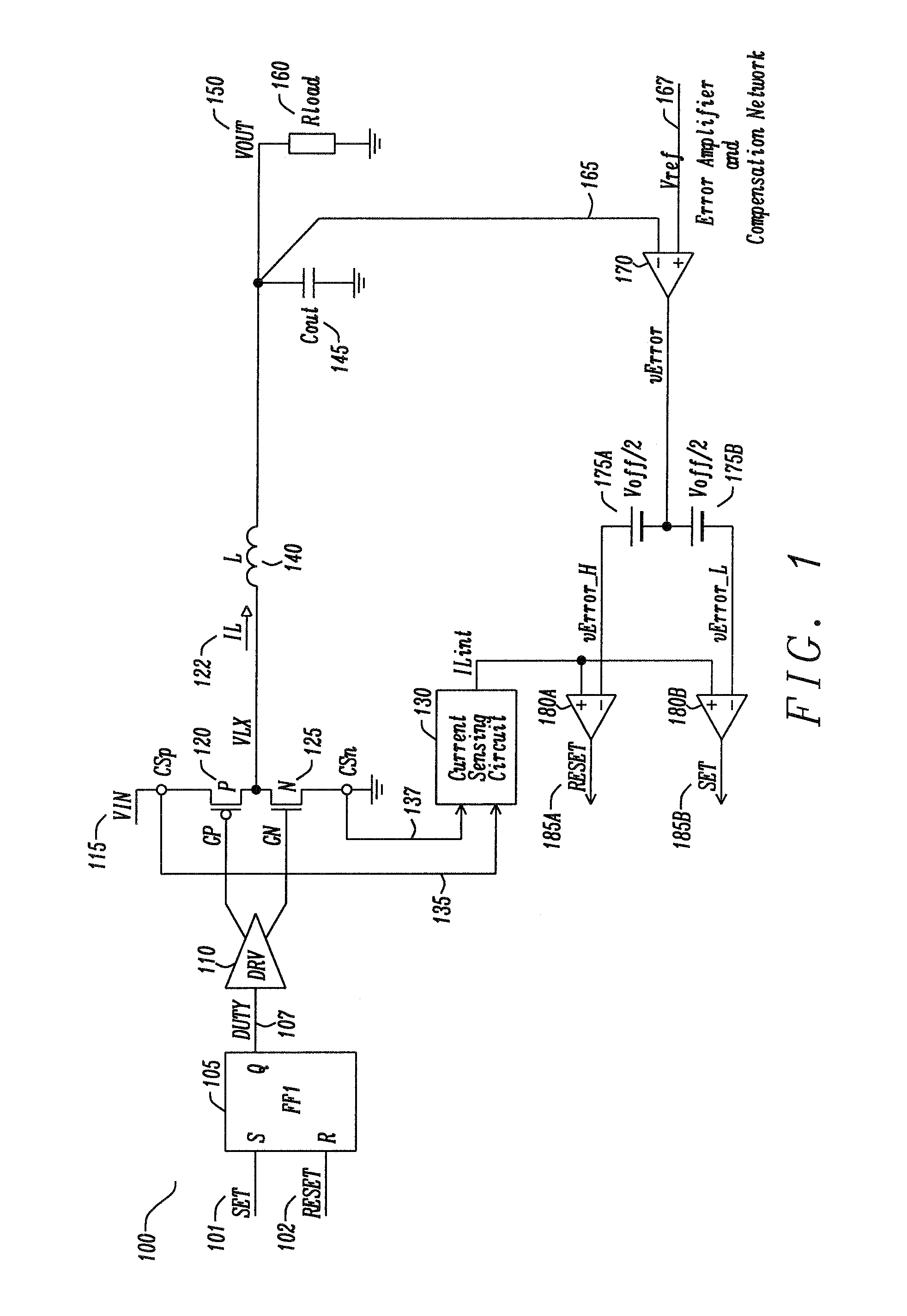
[0036]FIG. 3 is a circuit schematic in accordance with a first embodiment of the disclosure for a current mode voltage regulator. A simplified schematic of the controller is shown in FIG. 3. In this embodiment, the current in the coil for the positive current slope is not directly measured but it is estimated by the ‘Positive Slope Coil Current Estimator.’ The negative slope is measured via common current sensing circuitry marked as ‘CSn’ and ‘NMOS Current Sensing’ block. FIG. 3 shows the positive slope estimation is evaluated from the “pull-up” device (e.g. PMOS transistor) and negative sensing from the “pull-down” device (e.g. NMOS transistor). Note that the first embodiment of the disclosure can be modified where the slope estimation is evaluated from the “pull-down” device (e.g. NMOS transistor), and the current sensing from the “pull-up” device (e.g. PMOS transistor).

[0037]FIG. 3 shows a hysteretic current-mode controller 300. The controller, which is preferably a buck converte...


PUM


Abstract

A circuit and method for power converter for improved current monitoring, comprising a buck converter comprising a high side switch, a current sensing circuits parallel to the buck converter configured to sense a current through a low side switch, and a positive slope inductor coil estimator sensing circuit parallel to a buck converter configured to estimate a current magnitude.

Description

BACKGROUND[0001]1. Field[0002]The disclosure relates generally to a buck controller and, more particularly, to a control method using inductor coil current estimation thereof.[0003]2. Description of the Related Art[0004]Voltage regulation is important where circuits are sensitive to transients, noise and other types of disturbances. The control of the regulated voltage is key in switched mode power supplies (SMPS) and in many hysteretic-based topologies. Switched mode power supply topologies include the buck converter topology.[0005]In hysteretic-based topologies, one of the topologies includes a hysteretic current-mode (CM) topology.[0006]FIG. 1 shows a typical hysteretic current-mode controller. The buck converter 100 consists of a SR flip-flop 105 with inputs SET 101 and RESET 102. The SR flip-flop 105 provides a DUTY signal output 107 to pre-drive circuitry 110. The signal VIN 115 provides power to the output circuit comprising of a p-channel metal oxide semiconductor field effe...

Claims


Application Information

Patent Timeline
IPC IPC(8): G05F1/575
CPCG05F1/575H02M3/1588H02M1/0009
Inventor SVORC, JINDRICHKOBAYASHI, HIDENORI
Owner DIALOG SEMICON UK
Why Eureka
Try Eureka