Vehicle front section structure

Inactive Publication Date: 2015-07-02
TOYOTA JIDOSHA KK
View PDF17 Cites 12 Cited by
  • Summary
  • Abstract
  • Description
  • Claims
  • Application Information

AI Technical Summary

Benefits of technology

The present invention is a vehicle front section structure that allows the front side member to absorb adequate energy in the event of a head-on collision, even with a projection member attached outside of the front side member. The structure includes a closed cross-section portion formed by the inner and outer members of the front side member, with the projection member attached to the outer member and extending beyond it. In the event of a small overlap collision, the inner member deforms about the weakened portion where the projection member is located, while the outer member suppresses deformation to absorb collision energy. The front side member also allows for relative displacement between the two sides in the vehicle front-rear direction during a head-on collision. The inner and outer members are formed with upright flange portions that are spot welded together, and the spot welded locations separate efficiently to absorb collision energy. Overall, the vehicle front section structure exhibits excellent energy absorption performance and structural integrity in the event of a head-on collision.

Problems solved by technology

In such structures, however, the projection member functions as a reinforcement portion of the front side member in the event of a head-on collision, potentially lowering the energy absorption performance of the front side member.

Method used


Image

  • Vehicle front section structure
  • Vehicle front section structure
  • Vehicle front section structure

Examples


Embodiment Construction

Exemplary Embodiment Configuration

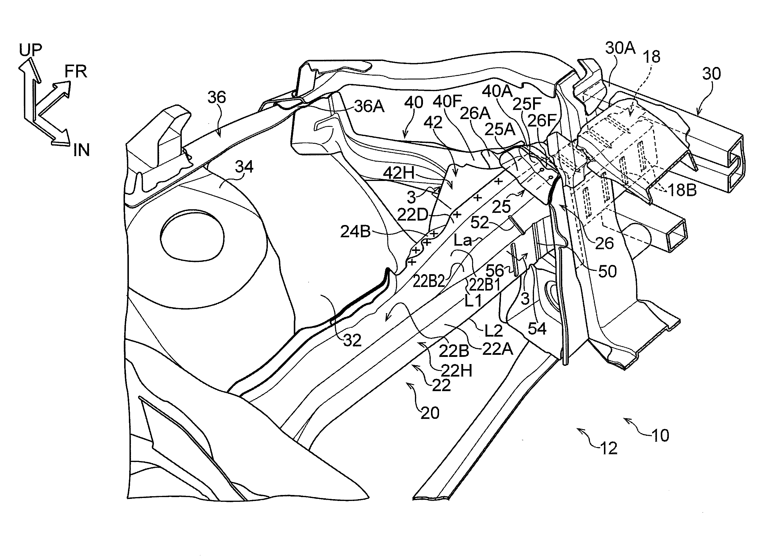
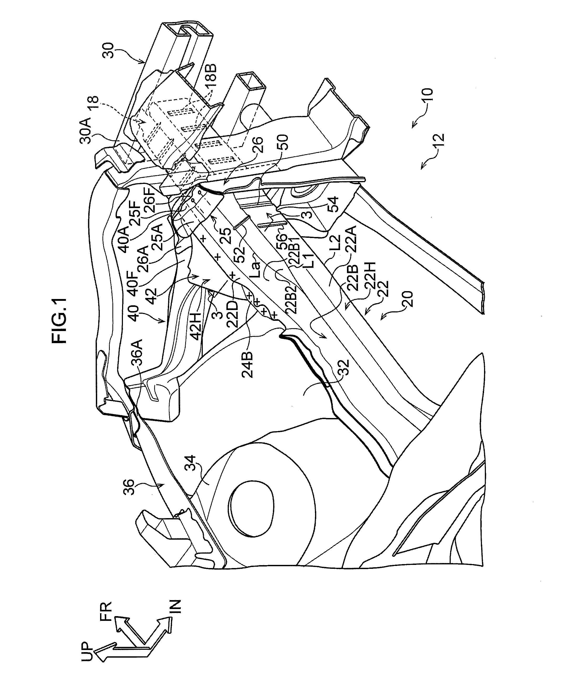
[0029]Explanation follows regarding a vehicle front section structure 10 according to an exemplary embodiment of the present invention, with reference to FIG. 1 to FIG. 4. In the drawings, the arrow FR indicates the vehicle front side, the arrow UP indicates the vehicle upper side, and the arrow IN indicates the vehicle width direction inside, as appropriate. In the following explanation, unless specifically indicated otherwise, reference to the front and rear, up and down, and left and right directions indicates the front and rear in the vehicle front-rear direction, up and down in the vehicle up-down direction, and left and right as facing in the direction of vehicle travel.

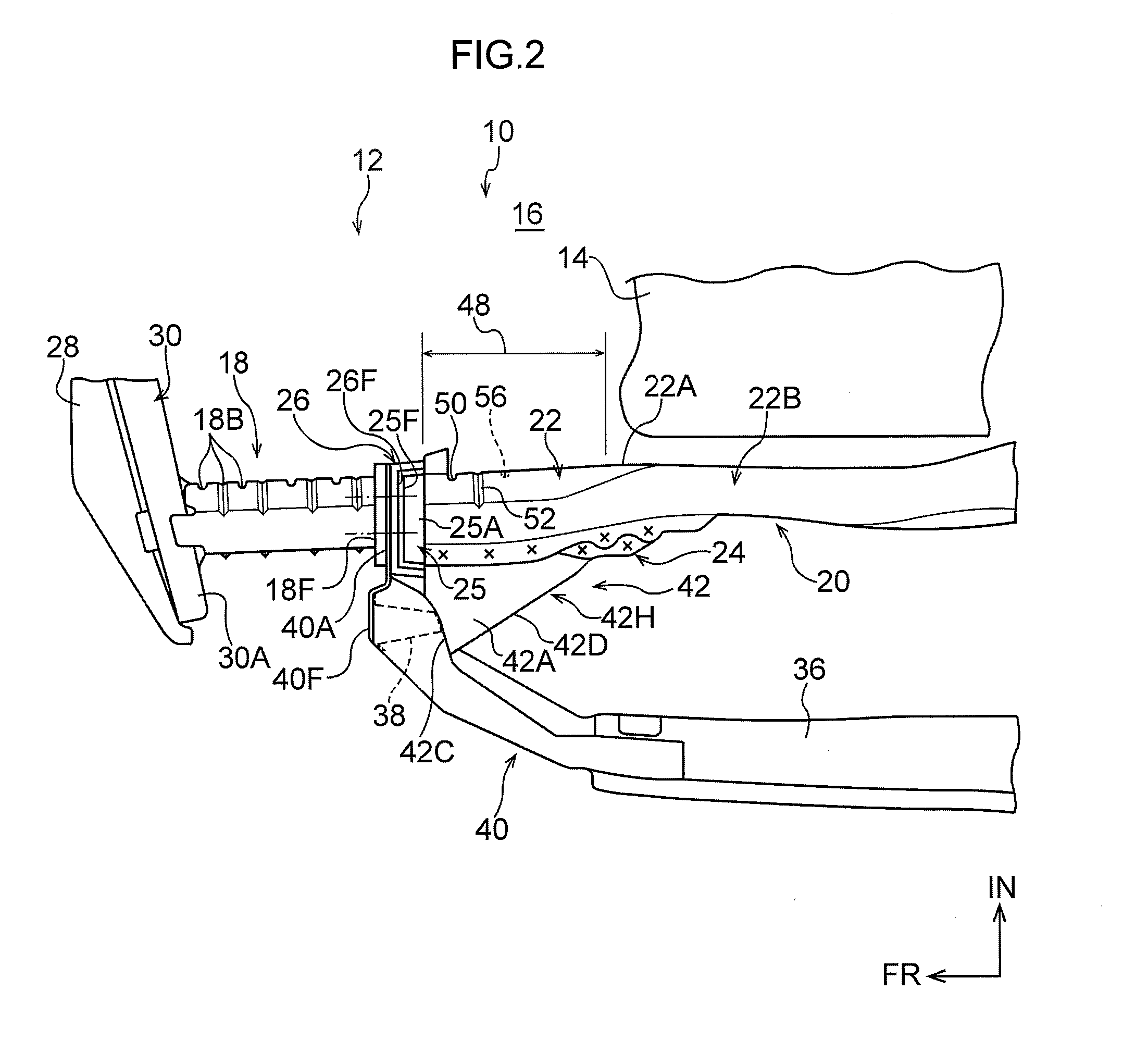
[0030]FIG. 1 is a perspective view illustrating the vehicle front section structure 10 according to the present exemplary embodiment, in a state viewed diagonally from the width direction inside and rear upper side of the vehicle. FIG. 2 is a plan view illustrating relevant por...


PUM


Abstract

There is provided a vehicle front section structure including: a front side member that is disposed along a vehicle front-rear direction at a vehicle width direction outside of a vehicle front section, and that includes an inner member and an outer member forming a closed cross-section portion extending in the vehicle front-rear direction; and a projection member disposed at the vehicle width direction outside of the front side member and attached to the outer member so as to project out further toward the vehicle width direction outside than the front side member, wherein a weakened portion is provided at the inner member in a vehicle front-rear direction range where the projection member is disposed.

Description

CROSS-REFERENCE TO RELATED APPLICATION[0001]This application is based on and claims priority under 35 USC 119 from Japanese Patent Application No. 2013-269982 filed on Dec. 26, 2013, the disclosure of which is incorporated by reference herein.BACKGROUND[0002]1. Technical Field[0003]The present invention relates to a vehicle front section structure.[0004]2. Related Art[0005]Vehicle front section structures exist in which a projection member such as a gusset is attached to a vehicle width direction outside face of a front side member, in order to improve collision performance in the event of a frontal collision (referred to hereafter as a “small overlap collision”) in which collision load is input at a vehicle width direction outside of the front side member (see for example Japanese Patent Application Laid-Open (JP-A) No. 2013-193572).[0006]In such structures, however, the projection member functions as a reinforcement portion of the front side member in the event of a head-on collis...

Claims


Application Information

Patent Timeline
IPC IPC(8): B62D25/08
CPCB62D25/082B62D21/155
Inventor SHIROOKA, MASAKAZU
Owner TOYOTA JIDOSHA KK
Why Eureka
Try Eureka