Container
- Summary
- Abstract
- Description
- Claims
- Application Information
AI Technical Summary
Benefits of technology
Problems solved by technology
Method used
Image
Examples
embodiment 1
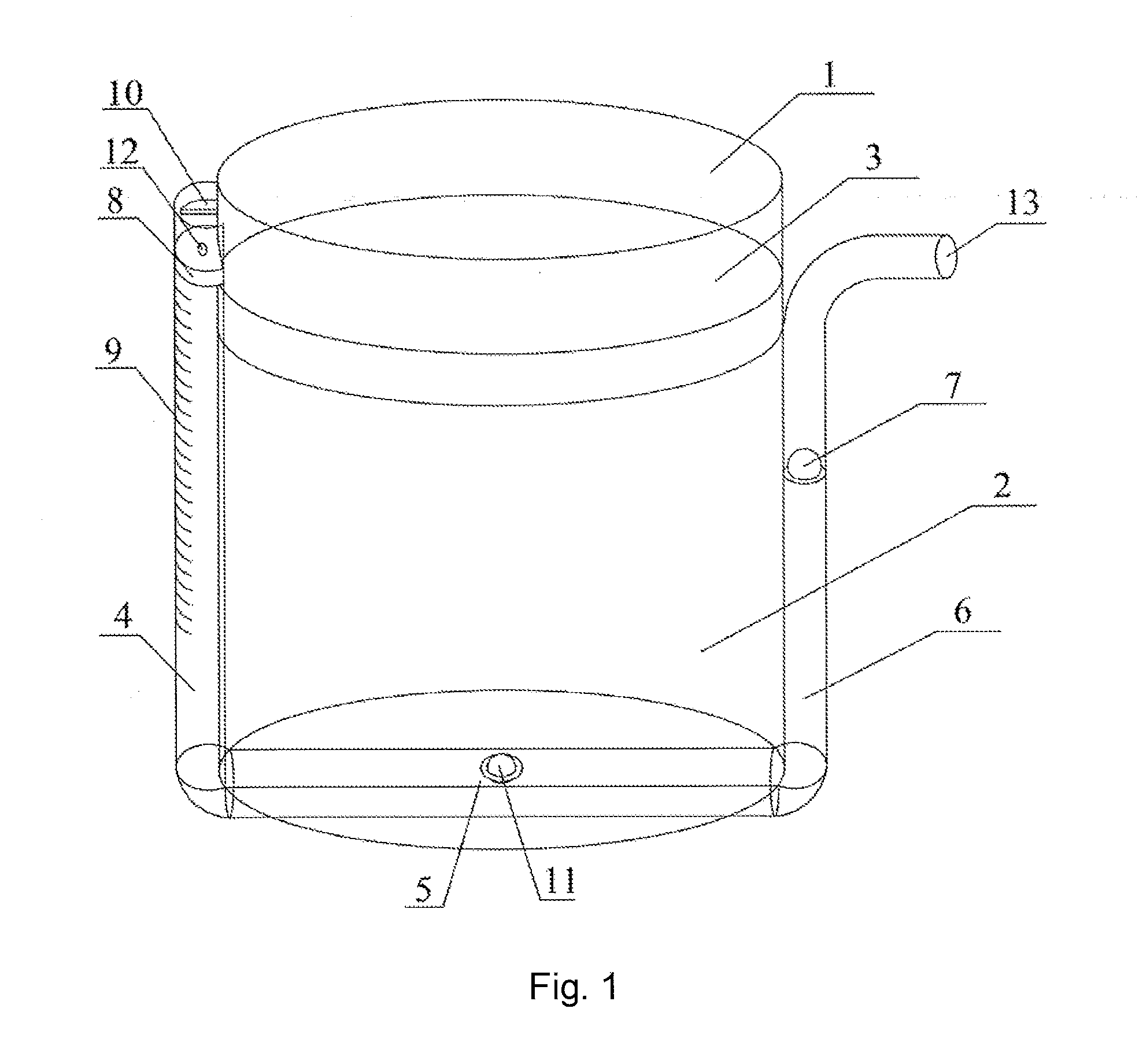
[0076]FIG. 1 shows a container according to Embodiment 1 of the present invention. A main body part 1 of the container is cylindrical and contains liquid contents 2, a piston 3 is located above the liquid contents, and the piston 3 can move vertically in the main body part 1. A pressure channel is disposed on a side wall of the main body part 1. The pressure channel is composed of a pressure transmission channel 4, a removal channel 5 and an outflow channel 6 connected in series, and is attached to the side wall and a bottom wall of the main body part.
[0077]The pressure transmission channel 4 is made of a transparent material, and has scales 9 marked. A piston 8 is disposed at an upper port of the pressure transmission channel 4, the piston 8 can move downwards along the pressure transmission channel 4, and a protrusion 10 stops the piston 8 from moving upwards. The piston 8 is provided with a screw hole 12 for connecting a pressurizing rod.
[0078]The removal channel 5 is provided wi...
embodiment 2
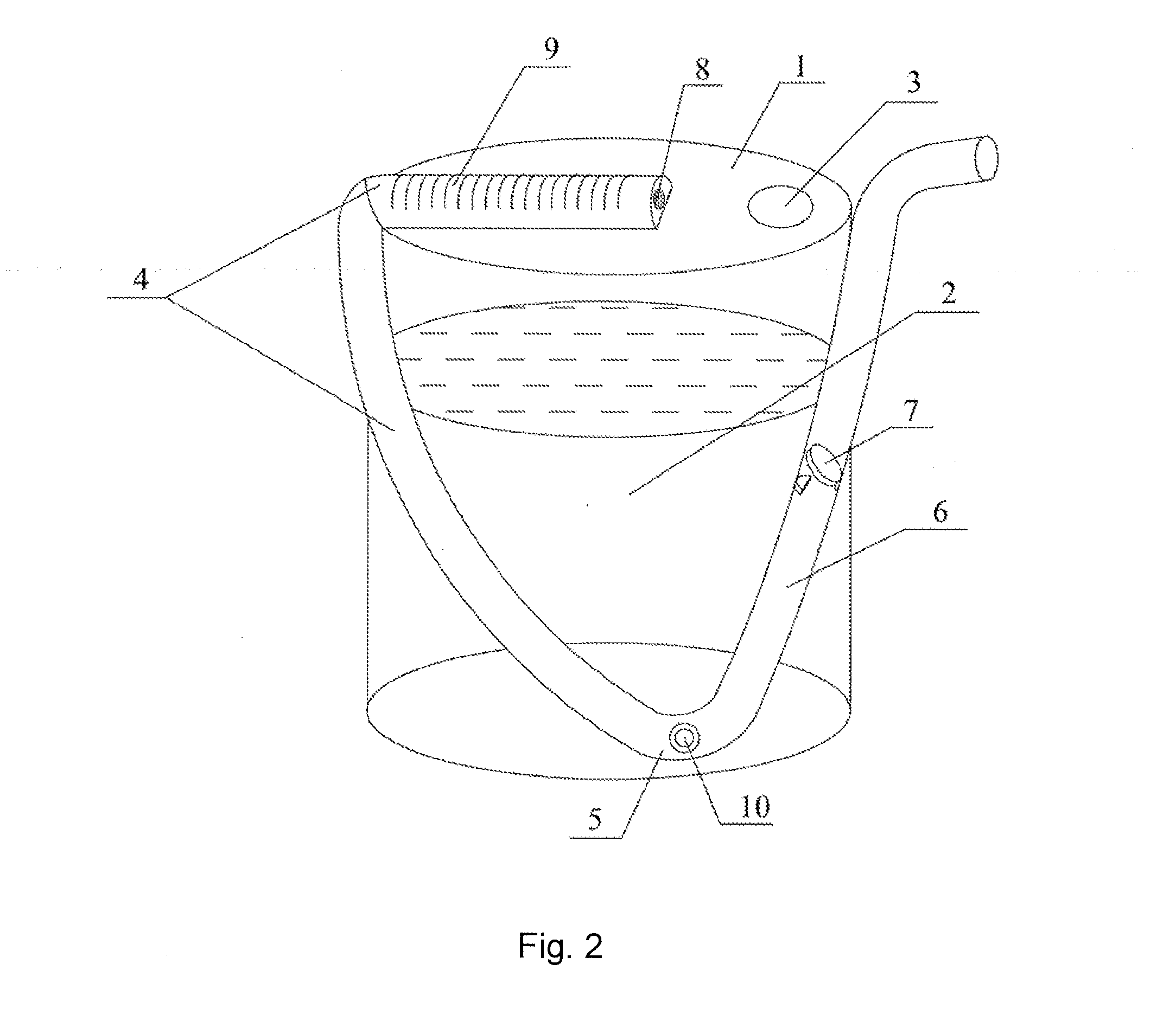
[0081]FIG. 2 shows a container according to Embodiment 2. The container includes a container main body 1, an upper part of the container main body 1 is provided with a filling opening, and after filling of the contents 2, the filling opening is sealed by using a membrane 3 merely allowing small molecular gas to pass through.
[0082]The container further includes a pressure channel attached to an upper wall and a side wall of the container main body 2 in an inclined manner, the pressure channel is composed of a pressure transmission channel 4, a removal channel 5 and an outflow channel 6 connected in series, and the pressure channel is located on the same plane. A part of the pressure transmission channel 4 is located on the upper wall of the container main body 1, and a part of the pressure transmission channel is located on the side wall of the container main body 1. A one-way valve 11 on the removal channel 5 is located at the lowest end of the pressure channel, and opens at a lower...
embodiment 3
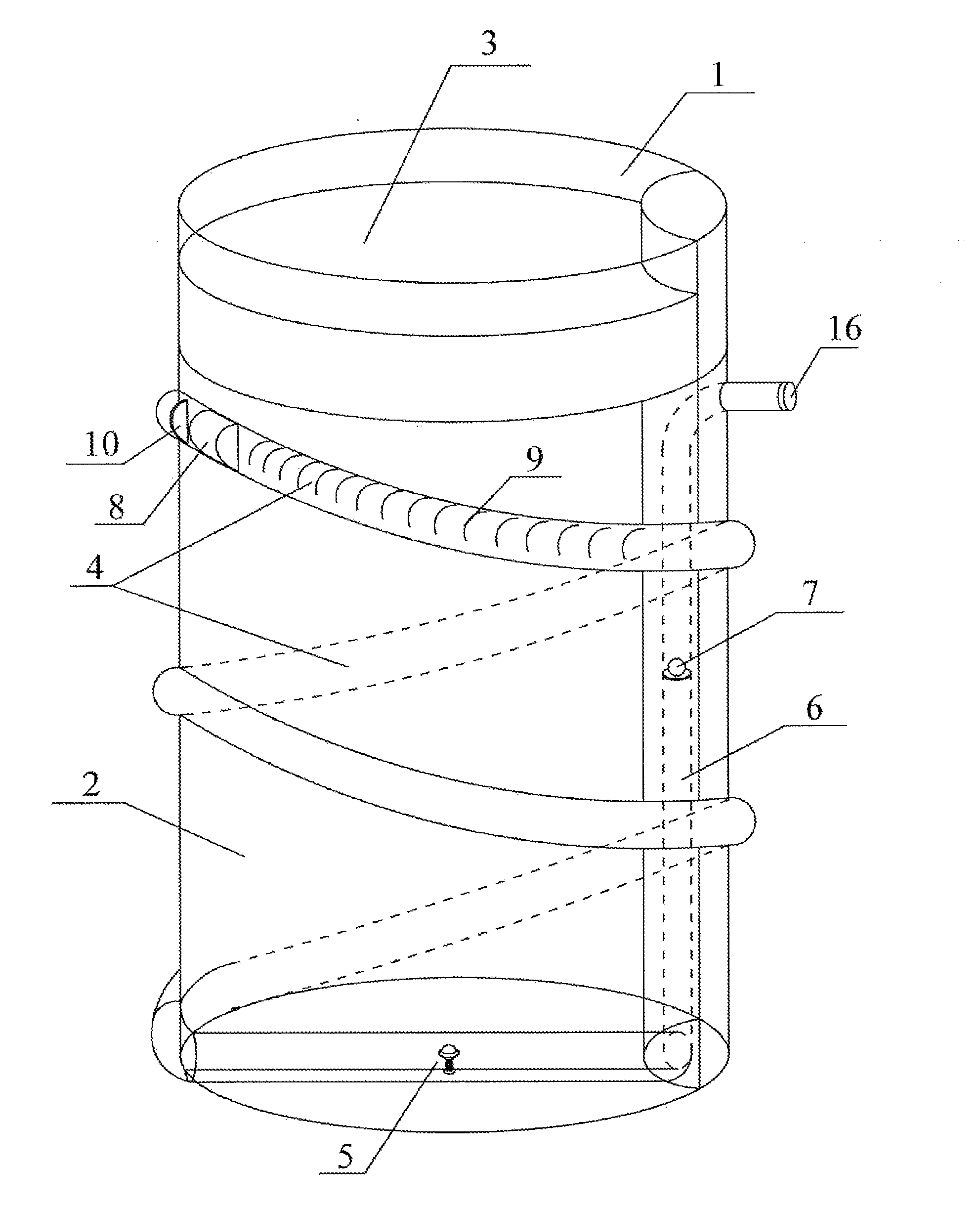
[0086]FIG. 3 and FIG. 4 show a container for containing contents according to Embodiment 3, and FIG. 4 is an enlarged diagram of a one-way valve. A main body part 1 of the container is cylindrical and contains liquid contents 2, a piston 3 is located above the liquid contents, and the piston 3 can move vertically in the main body part 1. A pressure channel is disposed on a side wall of the main body part 1. The pressure channel is composed of a pressure transmission channel 4, a removal channel 5 and an outflow channel 6 connected in series, and is attached to the side wall and a bottom wall of the main body part. The pressure transmission channel 4 is spirally attached to an outer wall of the main body part, the outflow channel 6 is attached to an inner wall of the main body part, and an opening of the outflow channel 6 is located outside the container.
[0087]The pressure transmission channel 4 is made of a transparent material, and has scales 9 marked. A piston 8 is disposed at an ...
PUM
 Abstract
Description
Claims
Application Information
 - R&D
- Intellectual Property
- Life Sciences
- Materials
- Tech Scout
- Unparalleled Data Quality
- Higher Quality Content
- 60% Fewer Hallucinations
Browse by: Latest US Patents, China's latest patents, Technical Efficacy Thesaurus, Application Domain, Technology Topic, Popular Technical Reports.
© 2025 PatSnap. All rights reserved.Legal|Privacy policy|Modern Slavery Act Transparency Statement|Sitemap|About US| Contact US: help@patsnap.com


