Control method for fuel filling system

a fuel tank and control method technology, applied in the direction of electrochemical generators, container discharging methods, packaged goods types, etc., can solve the problems of decreasing the prediction accuracy of the temperature inside the hydrogen tank, increasing the dissipation rate, etc., to accurately determine an abnormality in the sensor, accurately calculate the predicted value, and raise the prediction accuracy

Active Publication Date: 2015-07-02
HONDA MOTOR CO LTD
View PDF22 Cites 29 Cited by
  • Summary
  • Abstract
  • Description
  • Claims
  • Application Information

AI Technical Summary

Benefits of technology

[0017]With the fuel filling system of the first aspect of the present invention, fuel is filled in a filling mode determined based on the detected values of predetermined physical quantities detected by sensors and the unique information of the fuel tank. In addition, while filling fuel according to the step of determining in this way, the value of a predetermined physical quantity that is the detection target of a sensor is predicted based on the unique information, it is continuously confirmed whether this predicted value and the detected value of the sensor match, and in the case of an inconsistency between the detected value and predicted value being confirmed, the filling of fuel in the filling mode determined based on the unique information is interrupted. In the present invention, since the predicted value of a physical quantity is calculated using unique information of the fuel tank in this way, it is possible to accurately calculate the predicted value not only during the initial filling which can be adiabatically approximated, but also after initial filling in which it is necessary to release heat from the fuel tank. In addition, by using a predicted value calculated in this way, it is possible to accurately determine an abnormality in a sensor, fuel tank, etc. continuously during filling of fuel. In addition, according to the present invention, by calculating the predicted value based on the unique information of the fuel tank, since it is not necessary to decrease the filling flow rate in order to raise the prediction accuracy, the time required in filling will not lengthen more than necessary.
[0018]In the second aspect of the present invention, the value of a parameter related to the heat release characteristic of the fuel tank during the filling of fuel is included in the unique information as an input parameter for determining the filling mode, and further calculating predicted values. It is thereby possible to accurately calculate the predicted value of the temperature of fuel inside the fuel tank during fillin...

Problems solved by technology

This is because, a short time later after starting filling, the energy dissipation incr...

Method used


Image

  • Control method for fuel filling system
  • Control method for fuel filling system
  • Control method for fuel filling system

Examples


Embodiment Construction

[0026]Hereinafter, an embodiment of the present invention will be explained while referencing the drawings.

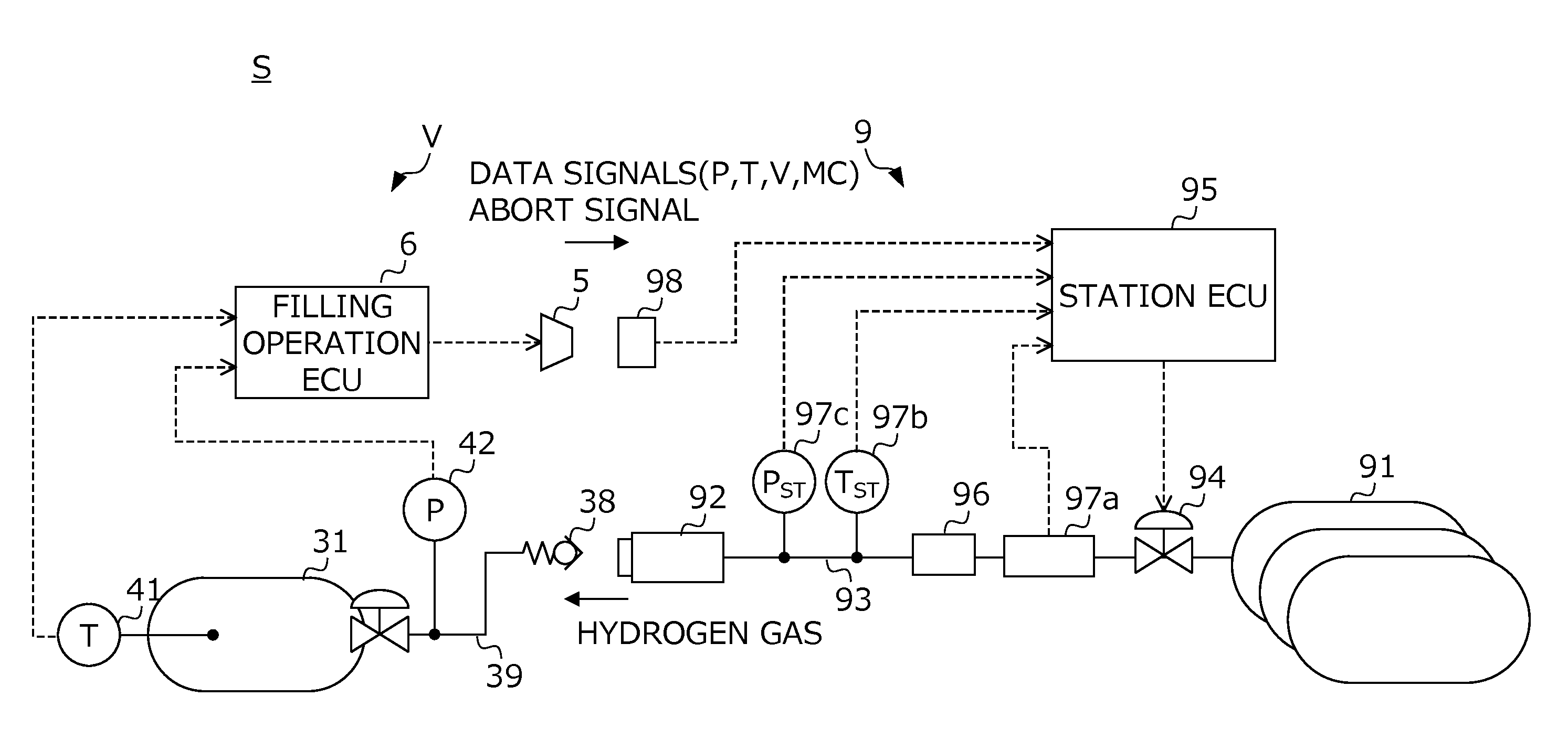
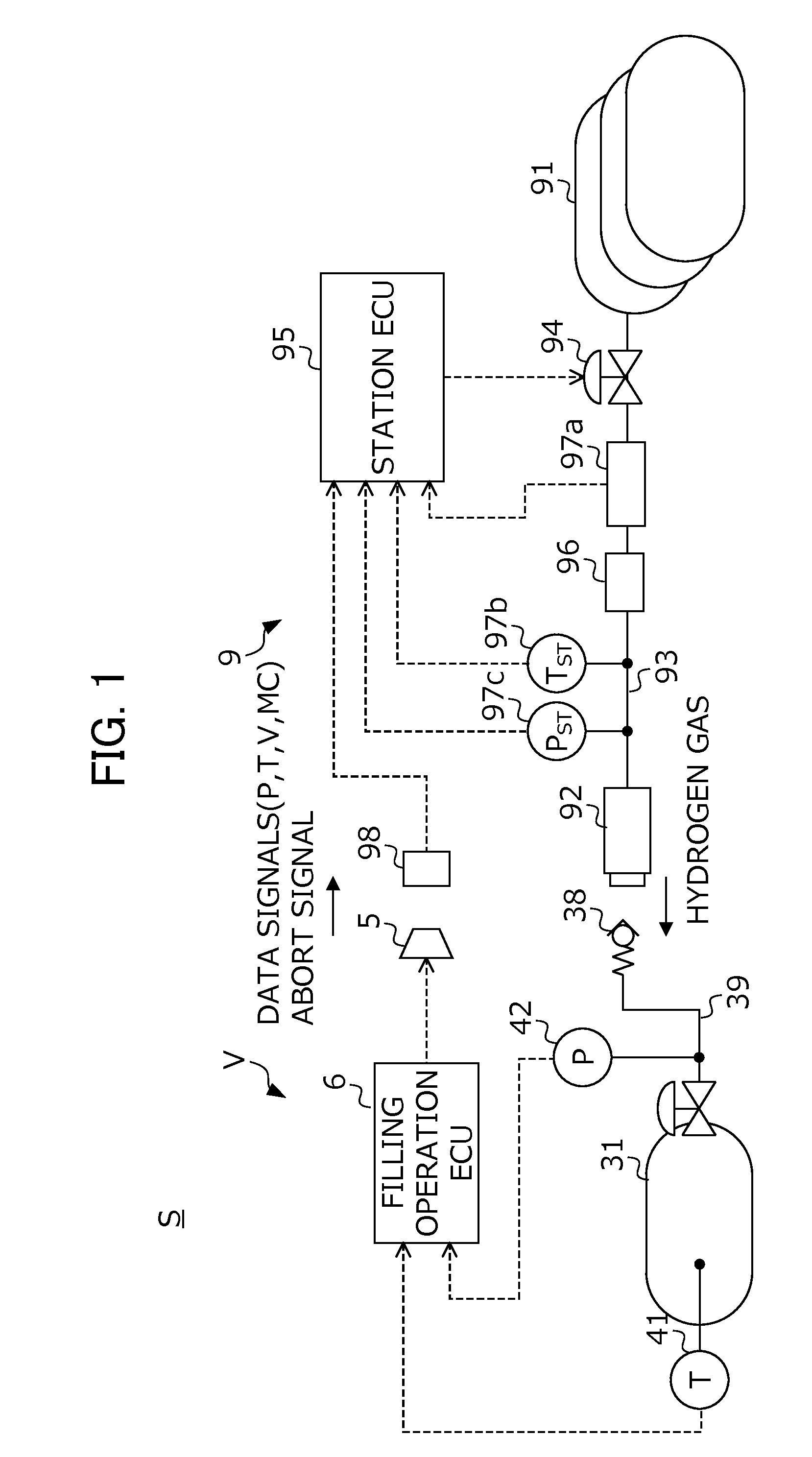
[0027]FIG. 1 is a view showing the configuration of a hydrogen filling system S related to the present embodiment. The hydrogen filling system S is configured by combining a fuel cell vehicle V that travels with hydrogen as fuel gas, and a hydrogen station 9 that supplies hydrogen fuel to a hydrogen tank 31 of this vehicle V. Hereinafter, the configuration on the hydrogen station 9 side will be explained first, and then the configuration of the fuel cell vehicle V side will be explained.

[0028]The hydrogen station 9 includes: a hydrogen storage tank 91 in which hydrogen gas for supplying the vehicle V is stored at high pressure, a filling channel 93 that leads from the hydrogen storage tank 91 to a filler nozzle 92 which is directly handled by an operator, a flow-rate control valve 94 that is provided in the filling channel 93, and a station ECU 95 that opens / closes the flow-rat...


PUM

PropertyMeasurementUnit
Temperatureaaaaaaaaaa
Pressureaaaaaaaaaa
Volumeaaaaaaaaaa

Abstract

A control method for a hydrogen filling system is provided. A hydrogen filling system (S) includes a vehicle (V) that sends unique information (V, MC) of the hydrogen tank and detected values (T, P) of sensors, and a station (9) that determines a filling mode based on this information (V, MC, P, T), and fills hydrogen to the tank in this determined mode. A station ECU (95) calculates predicted values (T′, P′) of the temperature and pressure inside of the hydrogen tank during filling of hydrogen based on the unique information (V, MC), continuously confirms whether the detected values (T, P) of the sensors and the predicted values (T′, P′) match while filling fuel, and in the case of an inconsistency between the detected values and predicted values being confirmed, interrupts filling of fuel in the filling mode determined based on the unique information.

Description

[0001]This application is based on and claims the benefit of priority from Japanese Patent Application No. 2013-269736, filed on 26 Dec. 2013, the content of which is incorporated herein by reference.BACKGROUND OF THE INVENTION[0002]1. Field of the Invention[0003]The present invention relates to a control method for a fuel filling system.[0004]2. Related Art[0005]Fuel cell vehicles travel by supplying air and hydrogen to the fuel cell, and driving an electric motor using the electric power thereby generated. In recent years, progress has been made in the practical implementation of fuel cell vehicles employing such fuel cells as the energy source for generating motive power. Hydrogen is required to generate electric power by fuel cells. In recent years, vehicles have become mainstream that store a sufficient amount of hydrogen in advance in a high-pressure tank or a hydrogen tank equipped with a storage alloy, and use the hydrogen inside of the tank to travel. In concert with this, ...

Claims


Application Information

Patent Timeline
IPC IPC(8): F17C5/06F17C13/02
CPCF17C5/06F17C13/026F17C13/028F17C2221/012F17C2250/034F17C2265/065F17C2250/0621F17C2250/075F17C2260/022F17C2260/023F17C2250/0631F17C2203/0604F17C2203/0646F17C2205/013F17C2223/0123F17C2223/036F17C2225/0123F17C2225/036F17C2227/0337F17C2227/04F17C2250/032F17C2250/043F17C2250/0439F17C2250/0636F17C2270/0168F17C2270/0184Y02E60/32
Inventor HANDA, KIYOSHI
Owner HONDA MOTOR CO LTD
Why Eureka
Try Eureka