Fiber Optic Gyroscope Sensing Coil and Method of Fabricating the Same

Active Publication Date: 2015-07-02
TOKYO KEIKI
View PDF4 Cites 5 Cited by
  • Summary
  • Abstract
  • Description
  • Claims
  • Application Information

AI Technical Summary

Benefits of technology

The present invention simplifies the process of winding optical fibers to create sensing coils, reducing the risk of winding deficiencies and making it easier to create a highly precise fiber optic gyroscope. The coil winding process is automated and carried out by machine, reducing labor and cost. The arrangement of the fiber sections ensures a symmetrical temperature distribution and cancels out any phase shifts in the light beams. Additionally, no jumps or cross-overs of optical fiber are produced, reducing mechanical stresses and improving the accuracy of the sensor.

Problems solved by technology

Fiber optic gyroscope sensing coils have an intrinsic problem in that they are sensitive to environmental factors such as temperature and vibration, or in other words, they have relatively poor environmental resistance.
There is, however, a problem with the coils wound in symmetrical winding configurations.

Method used


Image

  • Fiber Optic Gyroscope Sensing Coil and Method of Fabricating the Same
  • Fiber Optic Gyroscope Sensing Coil and Method of Fabricating the Same
  • Fiber Optic Gyroscope Sensing Coil and Method of Fabricating the Same

Examples


Embodiment Construction

[0056]Hereinafter, embodiments of the present invention will be described with reference to the accompanied drawings.

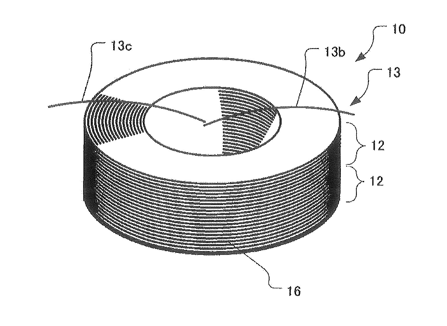
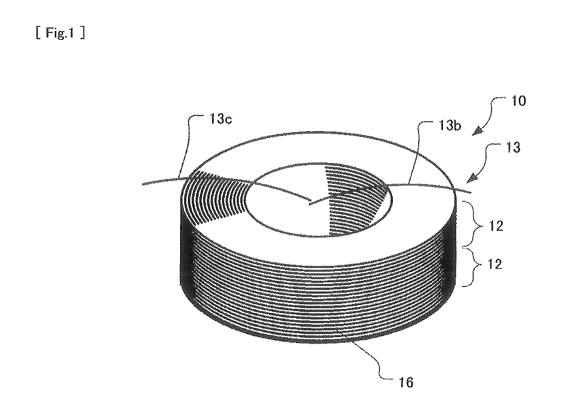
[0057]FIGS. 1 and 2 show a coil body 13 of a fiber optic gyroscope sensing coil 10 according to the present invention.

[0058]The coil body 13 of the fiber optic gyroscope sensing coil 10 includes two potted coils 12.

[0059]The potted coils 12 (one of which is shown in FIG. 2) have respective windings of optical fiber which are wound in an aligned winding configuration while the same tension is applied to optical fiber and at the same feed speed of optical fiber between the two potted coils 12. The windings of the potted coils 12 are each encapsulated within a potting material 16 such that adjacent turns of the optical fiber 14 in each winding are adhered with each other by the potting material 16. The optical fiber 14 may be a single-mode optical fiber (SM fiber) or a polarization-maintaining optical fiber (PM fiber).

[0060]The potting material 16 is preferably a soft ad...


PUM

PropertyMeasurementUnit
Elastic modulusaaaaaaaaaa

Abstract

A fiber optic gyroscope sensing coil, with which winding process of optical fiber may be simplified, crosstalk due to winding deficiencies may be reduced, and temperature sensitivity of gyroscope may be reduced.A coil body 13 includes two potted coils 12 having respective windings of optical fiber which are wound in an aligned winding configuration while the same tension is applied to optical fiber and at the same feed speed of optical fiber between the two potted coils and encapsulated within a potting material 16. The potted coils 12 are united together to form the coil body 13 by adhering the potted coils with each other at respective one side faces 12b thereof by using the potting material 16 as adhesive, and the tip ends of respective first fiber end sections 12c of optical fiber 14 of the potted coils 12, which are guided out from respective outermost layers of the windings of the potted coils 12, are connected with each other by fusing to form a continuous length of optical fiber of the coil body 13 wound in one direction.

Description

TECHNICAL FIELD[0001]The present invention relates to an optical fiber gyroscope sensing coil having improved environmental resistance and being easy to fabricate, as well as to a method of fabricating the same.BACKGROUND OF THE INVENTION[0002]Fiber optic gyroscope sensing coils have an intrinsic problem in that they are sensitive to environmental factors such as temperature and vibration, or in other words, they have relatively poor environmental resistance.[0003]For example, when a fiber optic gyroscope sensing coil is subject to a temperature variation, clockwise and counter-clockwise light beams propagating through the sensing coil may experience the effect of the temperature variation at different timings, which may induce phase shifts other than the Sagnac phase shifts in the light beams. The phase error due to the effect of a temperature variation is induced by the Shupe effect and called “Shupe error.”[0004]In order to reduce the Shupe error, there have been proposed various...

Claims


Application Information

Patent Timeline
IPC IPC(8): G01C19/72G01C25/00
CPCG01C25/00G01C19/722Y10T29/49885
Inventor YOSHIDA, TOYOORITAMAKI, TAKAYUKIKOJIMA, AKIHIKO
Owner TOKYO KEIKI
Why Eureka
Try Eureka