Production method for pre-filled syringe and pre-filled syringe production device

a production method and technology of syringe, applied in the direction of packaging goods, liquid handling, bundling machine details, etc., can solve problems such as deterioration of production efficiency

Inactive Publication Date: 2015-07-09
TERUMO KK
View PDF0 Cites 25 Cited by
  • Summary
  • Abstract
  • Description
  • Claims
  • Application Information

AI Technical Summary

Benefits of technology

[0032]According to the production method for a pre-filled syringe and the pre-filled syringe production device of certain embodiments, a gasket can quickly be inserted to a predetermined position upon inserting the gasket into an outer barrel.

Problems solved by technology

This might cause a a problem in a following foreign matter inspection.
When much time is taken for an insertion of the gasket in a process before a process of inspecting an insertion position of the gasket, a time lag is generated until the start of the inspection, resulting in deteriorated production efficiency.

Method used


Image

  • Production method for pre-filled syringe and pre-filled syringe production device
  • Production method for pre-filled syringe and pre-filled syringe production device
  • Production method for pre-filled syringe and pre-filled syringe production device

Examples


first embodiment

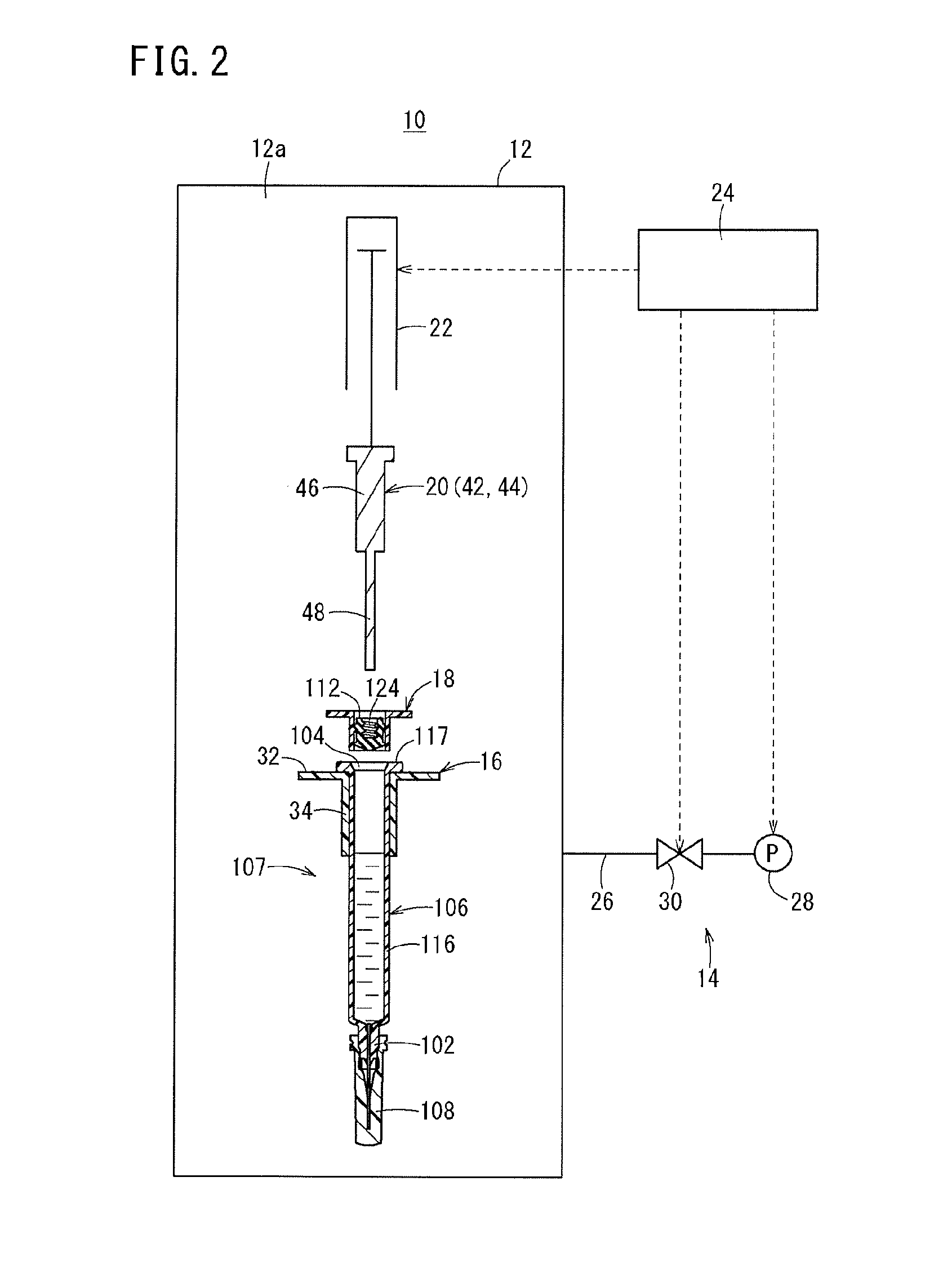
[0051]FIG. 2 is a view illustrating a schematic configuration of a pre-filled syringe production device 10 (hereinafter abbreviated to a “production device 10”) according to a first embodiment of the present invention. The production device 10 includes a chamber 12, a pressure control mechanism 14, a syringe holding member 16, a gasket holding member 18, a pushing member 20, an actuator 22, and a control unit 24.

[0052]The chamber 12 has a storage chamber 12a that can store an assembly having the barrel tip 102 sealed with the cap 108 and having the outer barrel 106 filled with the drug solution 110 with the barrel tip 102 being oriented at the bottom, and the gasket 112 (hereinafter referred to as a “syringe assembly 107”). The pressure in the storage chamber 12a can be reduced and also can be returned to the atmospheric pressure from the reduced state under the action of the pressure control mechanism 14.

[0053]Although not illustrated in FIG. 2, the chamber 12 has an opening into w...

second embodiment

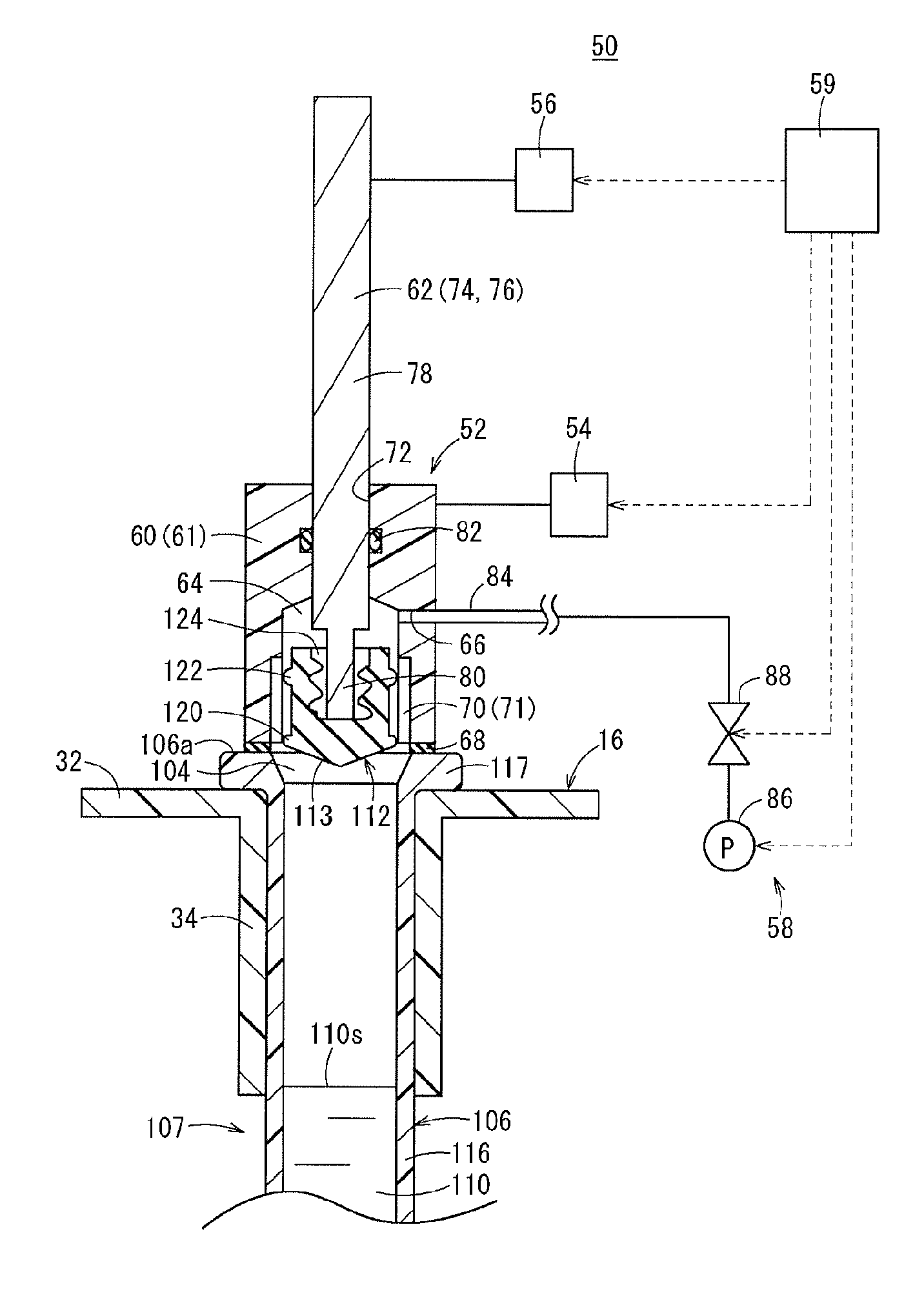
[0093]FIG. 5 is a view illustrating a schematic configuration of a pre-filled syringe production device 50 (hereinafter abbreviated to “production device 50”) according to a second embodiment of the present invention. This production device 50 includes a syringe holding member 16, a production jig 52, a jig moving mechanism 54, an actuator 56, a pressure control mechanism 58, and a control unit 59.

[0094]The syringe holding member 16 in the production device 50 has the same configuration as the syringe holding member 16 in the production device 10 according to the first embodiment. In the production device 50, the syringe holding member 16 is fixed to an appropriate position, or mounted detachably. The production device 50 may be configured to produce a plurality of pre-filled syringes 100 (see FIG. 1) from a plurality of sets of a syringe assembly 107 and a gasket 112. In this case, a number of syringe holding members 16 corresponding to the number of the sets are provided. In this ...


PUM

PropertyMeasurementUnit
speedaaaaaaaaaa
speedaaaaaaaaaa
speedaaaaaaaaaa

Abstract

A production method for a pre-filled syringe includes holding a syringe assembly; reducing a pressure in the outer barrel of the syringe assembly to a set pressure; while the pressure in the outer barrel of the syringe assembly is at the set pressure, sealing the proximal end opening of the outer barrel with the gasket by disposing the gasket at a sealing position; and pushing the gasket toward the barrel tip with a sliding motion through the outer barrel to move the gasket from the sealing position to an insertion position, and the insertion position being a position at which a distal end surface of the gasket is spaced from the drug solution. After the gasket is moved to the insertion position, a pressure in a space between the drug solution and the distal end surface of the gasket is approximately equal to the atmospheric pressure.

Description

CROSS-REFERENCE TO RELATED APPLICATIONS[0001]This application is a continuation application filed under 35 U.S.C. 111(a) claiming the benefit under 35 U.S.C. §§120 and 365(c) of PCT International Application No. PCT / JP2013 / 063210 filed on May 10, 2013, the entire contents of which is hereby incorporated by reference in its entirety.BACKGROUND[0002]1. Technical Field[0003]The present disclosure relates to a production method for a pre-filled syringe and a pre-filled syringe production device.[0004]2. Background Art[0005]A method for inserting a gasket into an outer barrel during a process of producing a pre-filled syringe has been proposed in which a proximal end opening of an outer barrel is sealed with the gasket with a pressure in the outer barrel being reduced, and the gasket is inserted to a predetermined position in the outer barrel due to a difference between a pressure inside the outer barrel and a pressure outside the outer barrel (atmosphere) (e.g., refer to JP 4-28386 B).[...

Claims


Application Information

Patent Timeline
Patent Type & Authority Applications(United States)
IPC IPC(8): A61M5/28B65B31/02
CPCA61M5/28B65B31/027A61M2207/10A61M2207/00A61M2209/045A61M5/1782B65B3/003B65B7/161B65B7/2821
Inventor OKIHARA, HITOSHIYAMASHITA, ARISA
Owner TERUMO KK
Why Eureka
Try Eureka