In-flight mechanically assisted turbine engine starting system

a technology of mechanical assistance and turbine engine, which is applied in the ignition of turbine/propulsion engine, instruments, navigation instruments, etc., can solve problems such as the effect of too long duration

Active Publication Date: 2015-07-09
SIKORSKY AIRCRAFT CORP
View PDF3 Cites 35 Cited by
  • Summary
  • Abstract
  • Description
  • Claims
  • Application Information

AI Technical Summary

Problems solved by technology

For a worst case condition where the engine has shut-down in

Method used


Image

  • In-flight mechanically assisted turbine engine starting system
  • In-flight mechanically assisted turbine engine starting system
  • In-flight mechanically assisted turbine engine starting system

Examples


Embodiment Construction

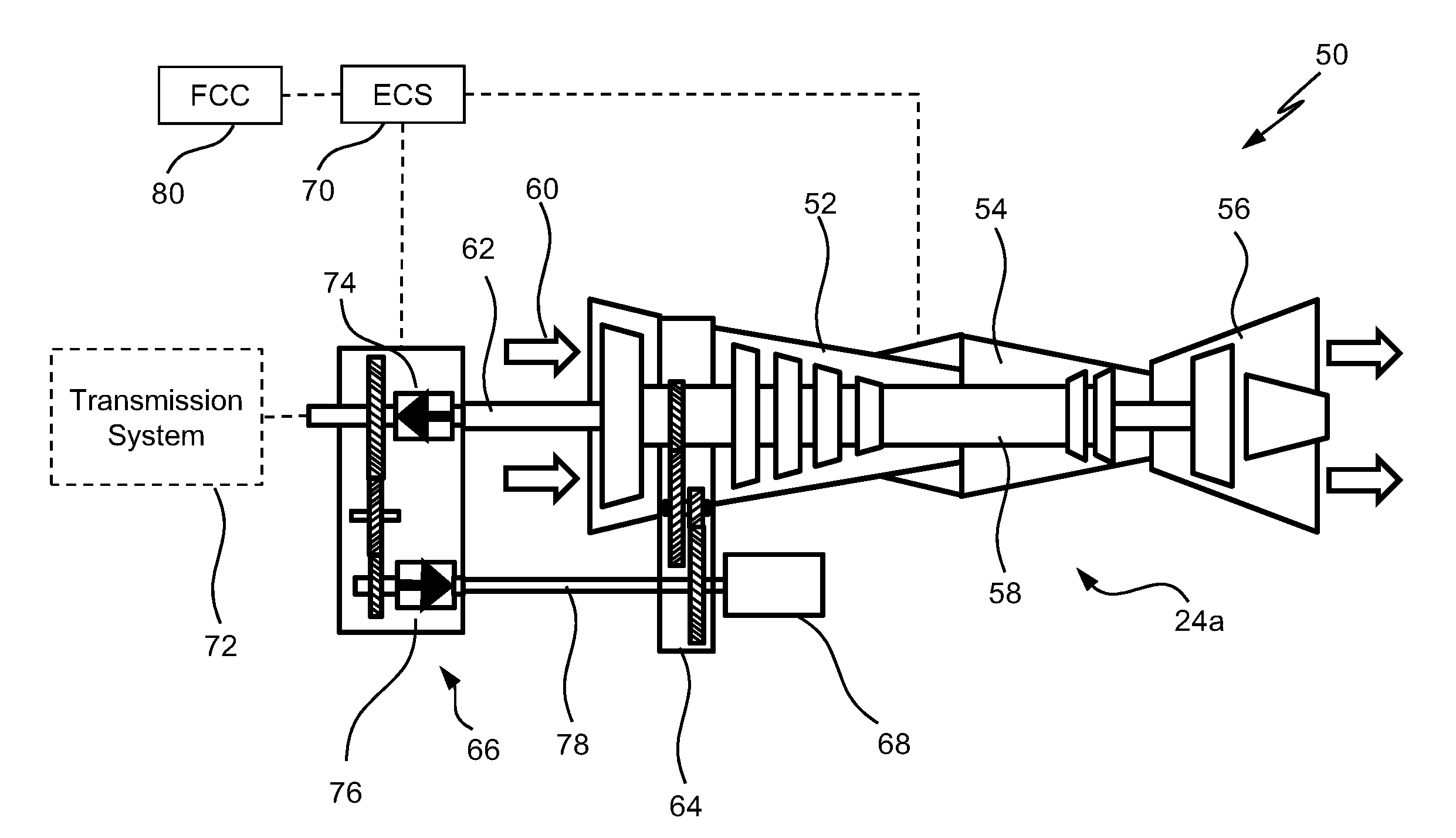
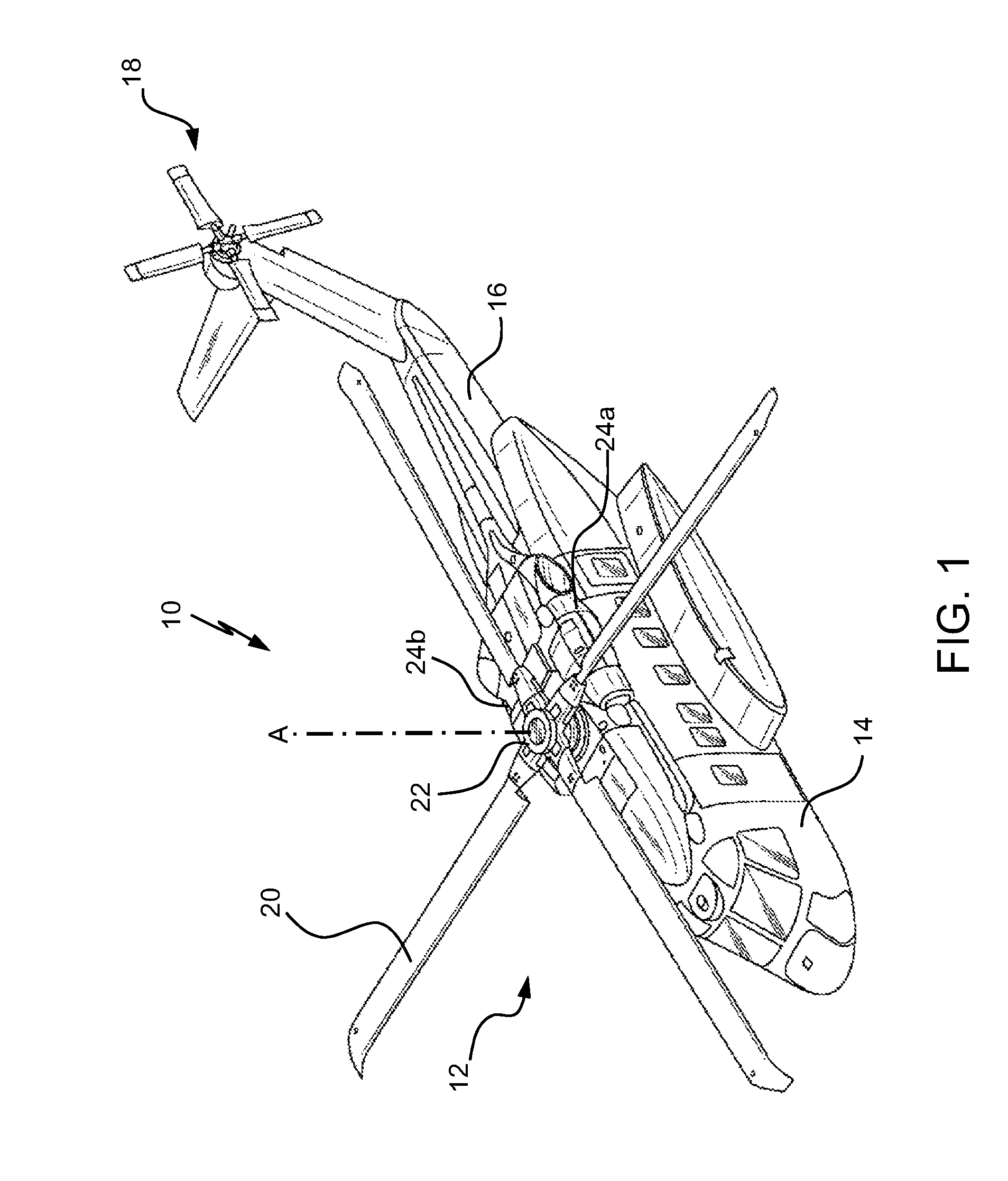
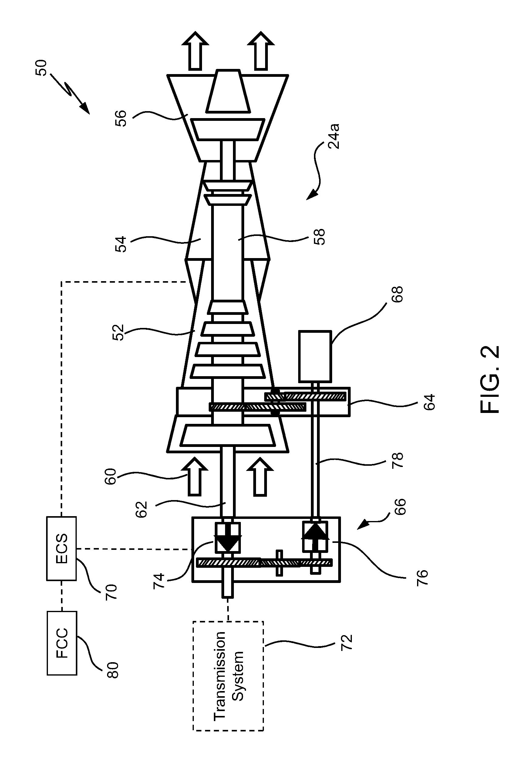
[0013]FIG. 1 schematically illustrates a rotary wing aircraft 10 which includes an in-flight turbine engine starting system according to an embodiment. The aircraft 10 includes an airframe 14 having a main rotor assembly 12 and an extending tail 16 which mounts a tail rotor system 18, such as an anti-torque system, a translational thrust system, a pusher propeller, a rotor propulsion system and the like. The main rotor assembly 12 includes a plurality of rotor blades 20 mounted to a rotor hub 22. The main rotor assembly 12 is driven about an axis of rotation A through a main rotor gearbox (not shown) by a multi-engine powerplant system, here shown as two internal combustion engines 24a-24b. The internal combustion engines 24a-24b generate the power available to the aircraft 10 for driving a transmission system that is connected to a main rotor assembly 12 and a tail rotor system 18 as well as for driving various other rotating components to thereby supply electrical power for flight...


PUM


Abstract

An engine starting system for a rotary wing aircraft includes a controller that receives a signal indicative of a start command for an engine, a transmission input module that is mechanically coupled to a transmission system and an accessory gearbox and a starter motor that is mechanically coupled to a compressor drive shaft of the engine. Also, a method for restarting an engine in flight includes receiving by a controller a signal indicative of a start command for the engine, determining by the controller that an overrunning clutch is coupled to the engine, transmitting by a transmission system motive power to the engine in response to the determining that the overrunning clutch is coupled to the engine and driving via a compressor drive shaft a compressor section of the engine according to a design speed.

Description

STATEMENT REGARDING FEDERALLY SPONSORED RESEARCH OR DEVELOPMENT[0001]This invention was made with Government support from the United States Air Force under Contract No. FA8650-09-D-2923. The Government therefore has certain rights in this invention.FIELD OF THE INVENTION[0002]The subject matter disclosed herein relates generally to propulsion systems and to, in particular, to a system and method for reliably starting a turbine engine in flight.DESCRIPTION OF THE RELATED ART[0003]Rotary wing aircraft utilize propulsion systems to power aircraft flight. These propulsion systems may include a turbine engine, a spark ignition engine, or a compression ignition engine. A turbine engine typically includes a compressor section, a combustion section, and a turbine section. The compressor section compresses air provided at an intake end of the gas turbine engine and provides the compressed air to the combustor section. Fuel is added to the compressed air, and the resulting mixture is ignited ...

Claims


Application Information

Patent Timeline
IPC IPC(8): B64D31/06B64C27/12B64D31/14F02C7/26
CPCB64D31/06F02C7/26F05D2260/85B64D31/14F05D2220/329B64C27/12F02C7/262F02C7/275F02C7/32F02C9/00F05D2260/43
Inventor DEVITA, MICHAEL JOSEPHBYSTRY, JR., MARK DENTON
Owner SIKORSKY AIRCRAFT CORP
Why Eureka
Try Eureka