Device for handling a wind turbine rotor blade

Active Publication Date: 2015-07-09
WOBBEN PROPERTIES GMBH
View PDF15 Cites 12 Cited by
  • Summary
  • Abstract
  • Description
  • Claims
  • Application Information

AI Technical Summary

Benefits of technology

[0007]One or more embodiments of the invention are directed to an apparatus for handling a

Problems solved by technology

The above-mentioned working steps become more difficult with increasing dimensions of the rotor blade and are the subject of an ever increasing amount of work and time, which has an adverse effect on the economy of rotor blades to be produced.
A disadvantage with those holders is that they are provided only for carrying out work along a single treatment position or section and, for carrying out working operations along a further treatment section, the rotor blade has to be undamped,

Method used


Image

  • Device for handling a wind turbine rotor blade
  • Device for handling a wind turbine rotor blade
  • Device for handling a wind turbine rotor blade

Examples


first embodiment

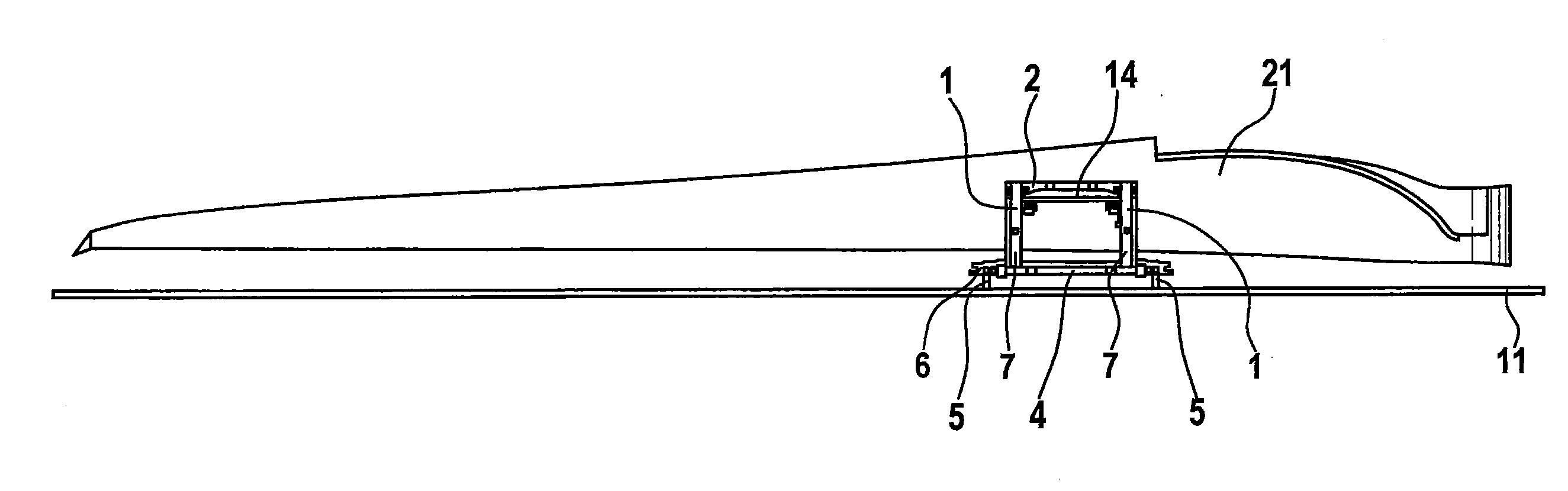
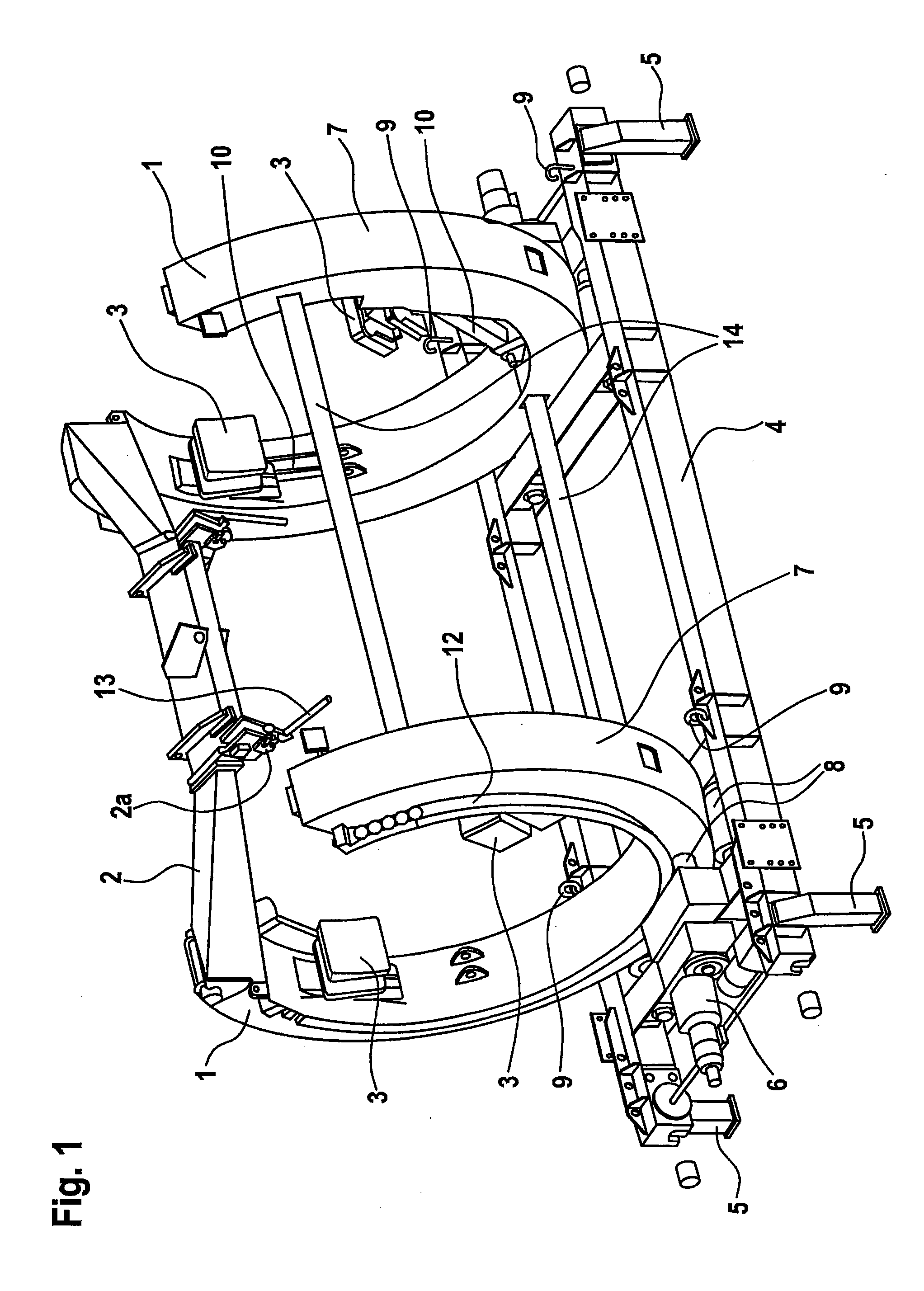
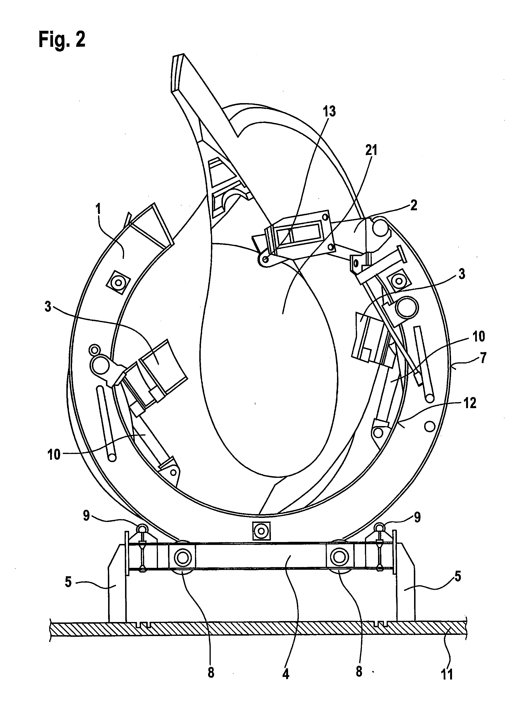
[0035]FIG. 1 shows a perspective view of an apparatus for handling a wind power installation rotor blade according to a The apparatus has a main body 1 (for example in the form of a rotary ring) with two C-shaped elements connected together by way of transverse bars 14. A pivotal portion or a pivotal bar or yoke 2 can connect first ends of the C-shaped rotary rings together. The main body 1 is mounted on a main frame 4 rotatably for example by means of rolling bearings 8. Provided on the main body 1 are contact portions 3 which partially or optionally have auxiliary arms 10 mounted rotatably or pivotably to the main body 1. The contact portions 3 can be in the form of strap supports and are provided for bearing against a rotor blade which is let down or introduced into the main body 1. The main body 1 has first large rolling surfaces 7 and second small rolling surfaces 12. The first and second rolling surfaces 7 and 12 form a connection with the rolling bearings 8 arranged on the m...

second embodiment

[0053]FIG. 7 shows a cross-section through the FIG. 6 apparatus. The handling apparatus of the second embodiment has a main frame 4, a main body 1 mounted rotatably thereon for receiving the rotor blade, and a fixing device 30. The fixing device 30 has first and second portions 31, 32. The first portion 31 of the fixing unit 30 has a load or locking pin 33, rotatable wheels 35 and a spring 36 for example for prestressing the pin 33. The second portion 32 also has a pin 34 and a spring 37 for prestressing the pin. The rotor blade can be locked in the handling apparatus by those load pins 33, 34.

[0054]FIG. 8 shows a perspective view of the apparatus for handling a wind power installation rotor blade according to the second embodiment. The handling apparatus has a main frame 4 and a main body 1 mounted rotatably thereon. The main body 1 comprises for example two C-shaped and annular rotary rings having an opening, through which a rotor blade of a wind power installation can be introduc...


PUM


Abstract

There is provided an apparatus for rotating and/or displacing a rotor blade of a wind power installation. The apparatus has at least one main body for at least partially embracing the rotor blade with a longitudinal, at least one contact portion for bearing against the rotor blade and at least one main frame for receiving the main body for rotation of the main body about the longitudinal axis and/or for displacement of the main body. The main body has at least one pivotably mounted pivotal portion for engagement at at least one side of the rotor blade.

Description

BACKGROUND[0001]1. Technical Field[0002]The invention concerns an apparatus for handling a rotor blade of a wind power installation, in particular for holding the rotor blade and performing rotary and / or translatory movements.[0003]2. Description of the Related Art[0004]The construction and manufacture of a rotor blade up to definitive mounting thereof at the location of use are effected in a plurality of working and process steps. In the course of those operations the rotor blade has to be repeatedly lifted, turned, displaced and changed in terms of the way it is clamped to make various regions on the rotor blade accessible for the operations to be performed. The above-mentioned working steps become more difficult with increasing dimensions of the rotor blade and are the subject of an ever increasing amount of work and time, which has an adverse effect on the economy of rotor blades to be produced.[0005]Fixedly anchored holders for clamping rotor blades are known from the state of ...

Claims


Application Information

Patent Timeline
IPC IPC(8): F03D1/00
CPCF03D1/005F03D13/40Y02E10/72Y02B10/30F03D13/10Y02P70/50
Inventor LULKER, FRANKBRENNER, ALBRECHT
Owner WOBBEN PROPERTIES GMBH
Why Eureka
Try Eureka