Display device and light emitting device
a technology of light-emitting devices and display devices, which is applied in semiconductor devices, lighting and heating apparatus, instruments, etc., can solve the problems of uneven light irradiation to the lcd panel, affecting the brightness affecting the performance of the lcd, so as to ensure the brightness uniformity of the display device, reduce the space between the light-emitting device and the lcd panel, and reduce the thickness of the display device
- Summary
- Abstract
- Description
- Claims
- Application Information
AI Technical Summary
Benefits of technology
Problems solved by technology
Method used
Image

Examples
first embodiment
[0051]FIG. 4 is an exploded perspective view showing a display device and FIG. 5 is a sectional view taken along the line A-A′ of FIG. 4.
[0052]Referring to FIGS. 4 and 5, an LCD (Liquid Crystal Display) 140 according to the embodiment includes a BLU (Back Light Unit) 150 and an LCD panel 160, a panel control substrate 171 and 173, a panel guider 180 and an upper case 190.
[0053]The BLU 150 performs a function of generating and outputting light. According to the embodiment, the BLU 150 is implemented in a direct type. The BLU 150 includes a lower cover 151, a light emitting device 153 and at least one optical sheet 159.
[0054]The lower cover 151 has a shape of a box, a top surface of which is opened. The lower cover 151 receives the light emitting device 153 through an upper portion thereof, and support and protects the light emitting device 153. In addition, the lower cover 151 supports the optical sheet 159 and the LCD panel 160. The lower cover 151 may be made of metal. For example...
second embodiment
[0068]Only, the light emitting device 200 of the second embodiment further includes reflective portions 233. The reflective portions 233 are mounted on the drive substrate 230. The reflective portions 233 surround the light flux control member 220. The reflective portions 233 protrude more than a mounting surface 232. The sectional shape of the reflective portions 233 may be triangular, rectangular, diamond or semicircular.
[0069]Meanwhile, although the light flux control member including the incident surface, the reflective surface, the first and second refractive surfaces and the back surface has been described in the above embodiment as one example, the embodiment is not limited thereto. For example, even if the light flux control member has no second refractive surface, the embodiment can be implemented, which will be described below in detail.
third embodiment
[0070]FIG. 8 is a sectional view showing a light emitting device according to the
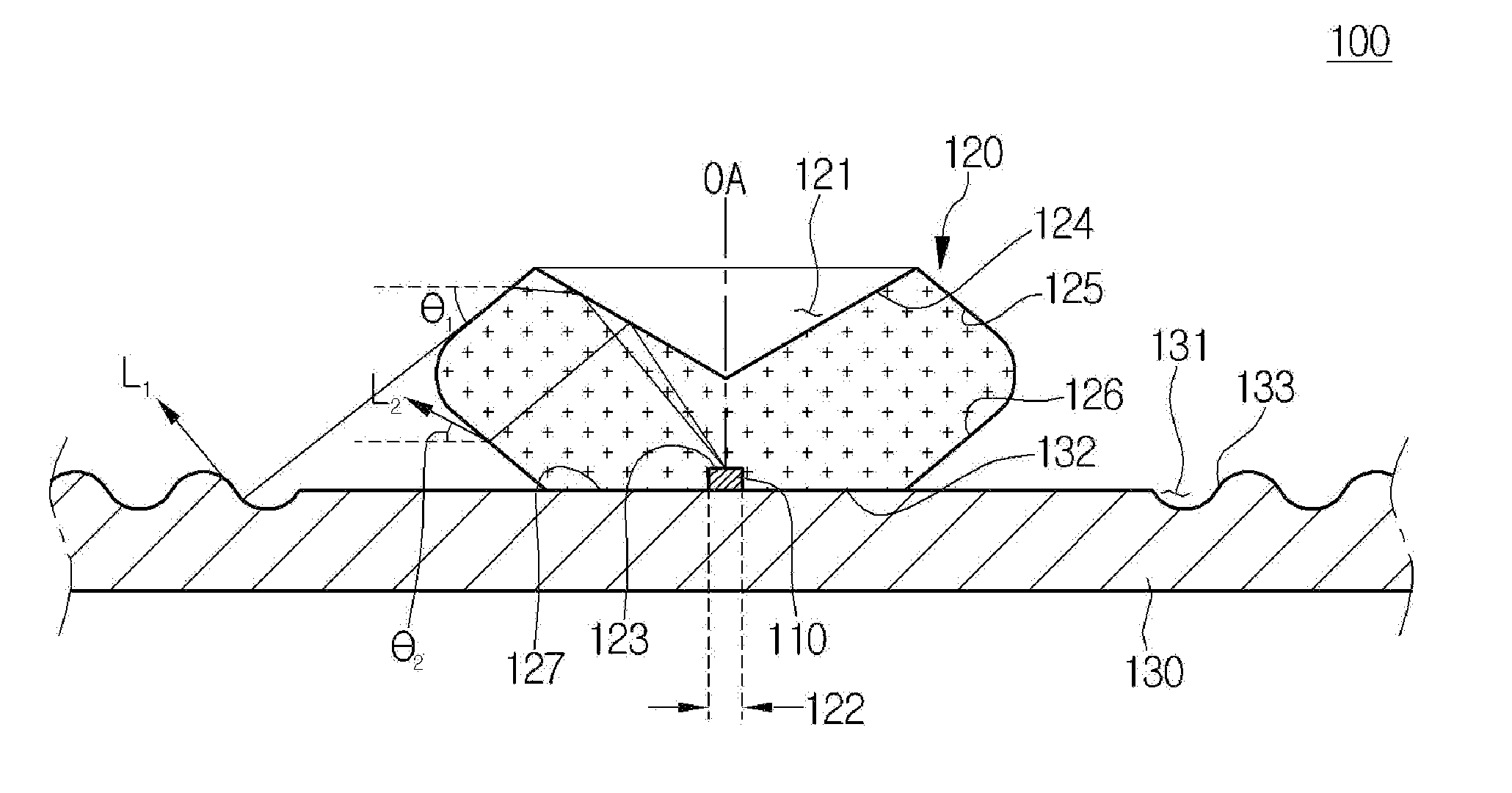
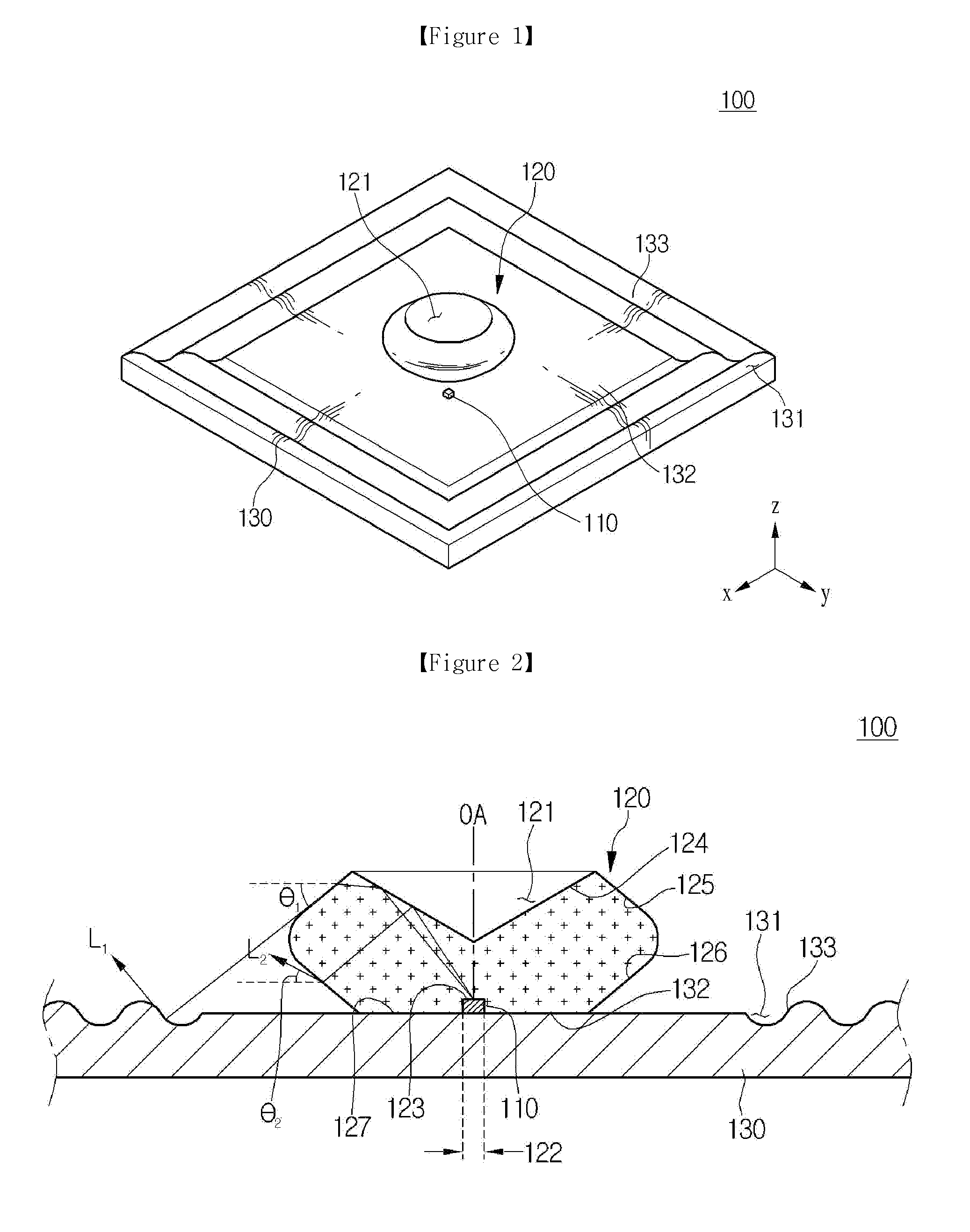
[0071]Referring to FIG. 8, the light emitting device 300 according to the third embodiment includes a light source 310, a light flux control member 320 and a drive substrate 330. The light flux control member 320 includes a depressed portion 321 and a groove portion 322 formed therein. The light flux control member 320 includes an incident surface 323, a reflective surface 324, a first refractive surface 325, and a back surface 327. Since the elements of the light emitting device according to the third embodiment are the same as or similar with the corresponding those of the above-described embodiments, the detailed description will be omitted.
[0072]In the light emitting device 300 of the third embodiment, the first refractive surface 325 is extended from the reflective surface 324 and is connected to the back surface 327. The distance between the first refractive surface 325 and the optical axis OA of ...
PUM
 Abstract
Description
Claims
Application Information
 - R&D
- Intellectual Property
- Life Sciences
- Materials
- Tech Scout
- Unparalleled Data Quality
- Higher Quality Content
- 60% Fewer Hallucinations
Browse by: Latest US Patents, China's latest patents, Technical Efficacy Thesaurus, Application Domain, Technology Topic, Popular Technical Reports.
© 2025 PatSnap. All rights reserved.Legal|Privacy policy|Modern Slavery Act Transparency Statement|Sitemap|About US| Contact US: help@patsnap.com