Apparatus and Process for Producing Acknowledged Air Flow and The Use of Such Apparatus in Measuring Particle Concentration in Acknowledged Air Flow

a technology of acknowledged air flow and apparatus, which is applied in the direction of separation processes, instruments, mass spectometers, etc., can solve the problems of ion wind change and other problems, and achieve the effect of accurate sensor base and fast determination of acknowledged flow

Active Publication Date: 2015-07-09
PEGASOR OY
View PDF2 Cites 9 Cited by
  • Summary
  • Abstract
  • Description
  • Claims
  • Application Information

AI Technical Summary

Benefits of technology

[0023]In the invented process the switching / modulation frequency of a parameter affecting the sensing element output may between 0.01 Hz and 10 Hz, thus providing a fast determination of the acknowledged flow and thus providing accurate basis for sensors where air flow through the sensor is required.
[0024]The essential parameters can be determined even continuously when required e.g. due to rapidly changing aerosol composition. If the changes in the measurement environment are not remarkable on a short time interval, and when the maximum time response of the measurement is required, the determination of the essential parameters may be carried out with longer intervals.

Problems solved by technology

Although the ion wind generated by a corona discharge unit may stay stable with clean air and with short time intervals, there is a tendency for the ion wind to change due to changes in corona geometry or corona tip soiling.

Method used


Image

  • Apparatus and Process for Producing Acknowledged Air Flow and The Use of Such Apparatus in Measuring Particle Concentration in Acknowledged Air Flow
  • Apparatus and Process for Producing Acknowledged Air Flow and The Use of Such Apparatus in Measuring Particle Concentration in Acknowledged Air Flow
  • Apparatus and Process for Producing Acknowledged Air Flow and The Use of Such Apparatus in Measuring Particle Concentration in Acknowledged Air Flow

Examples


Embodiment Construction

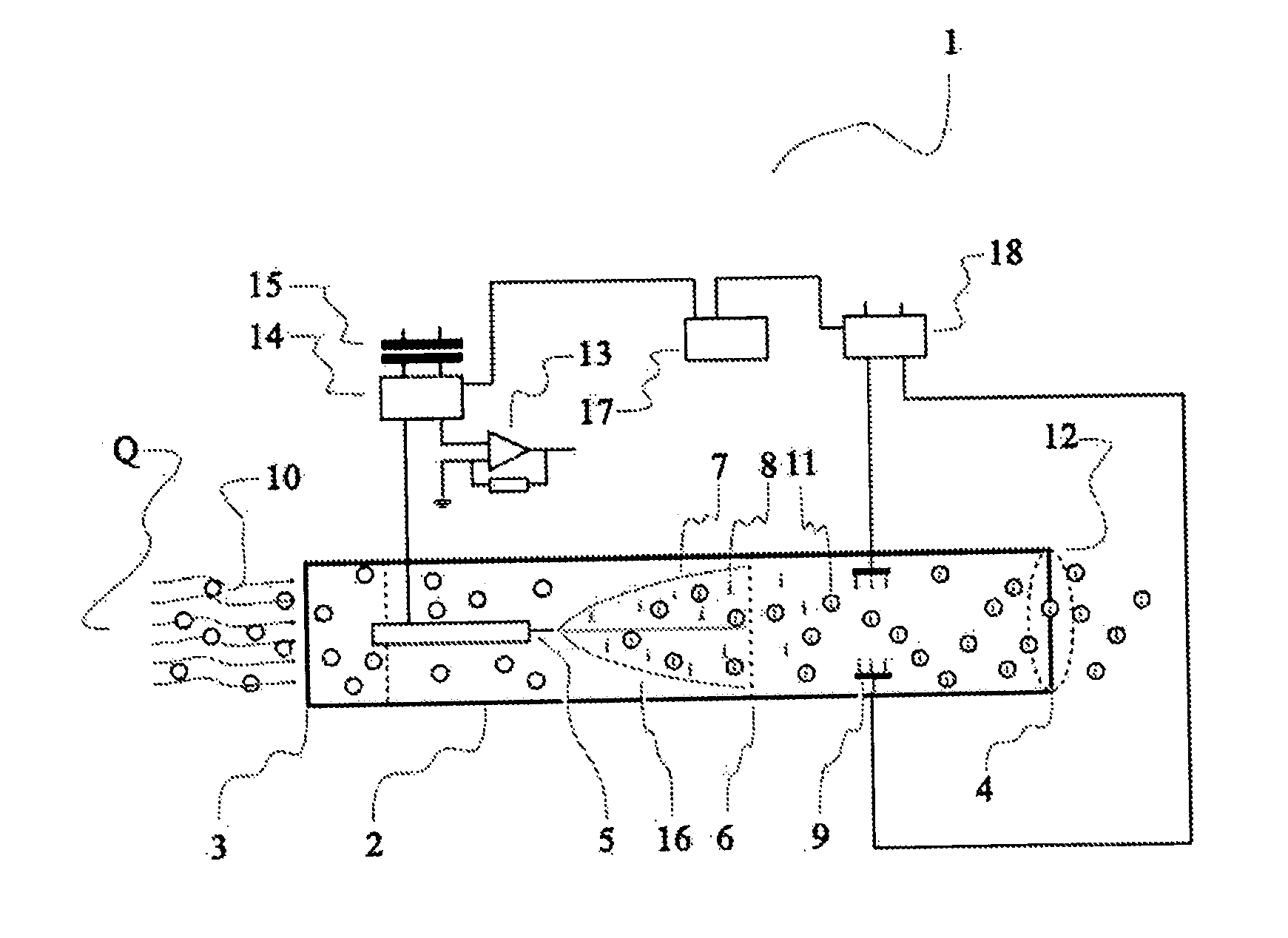
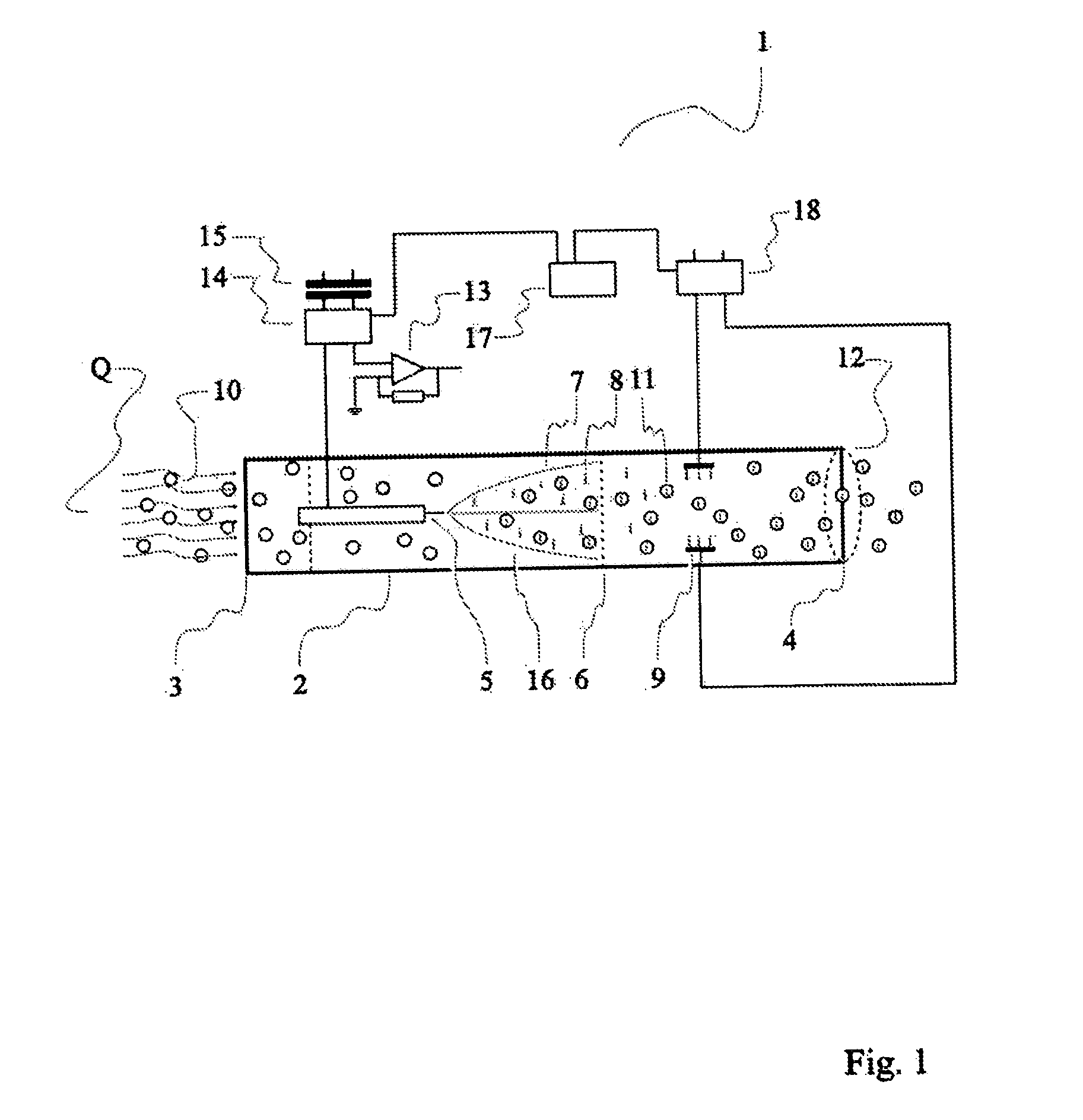
[0028]FIG. 1 shows the invented apparatus 1 for generating acknowledged flow Q. Apparatus 1 comprises a first passage 2 with ends 3, 4 for the inlet and outlet of the acknowledged flow Q. The first passage 2 is preferably designed so that it generates a pressure difference of less than 20 Pa with the documented flow Q, more preferably less than 10 Pa and most preferably less than 5 Pa, as such pressure levels can be typically achieved by using electric wind to generate flow. In most cases the ends 3, 4 of the first passage 2 are essentially free. Inside passage 2 is a discharge electrode 5 powered from a high voltage source 14, which is isolated from mains with an isolation transformer 15. Discharge electrode 5 is adapted for generating airborne unipolar ions 8 and a counter electrode 6 is adapted to attract said airborne ions 8, thereby being adapted to cause a net flow 7 of airborne ions 8 and thereby generating an airflow Q in the direction of the net flow of airborne ions 8. App...


PUM

PropertyMeasurementUnit
modulation frequencyaaaaaaaaaa
switching/modulation frequencyaaaaaaaaaa

Abstract

Apparatus (1) for generating acknowledged flow (Q), comprising a first passage (2) with ends (3,4) for acknowledged flow (Q) inlet and outlet, a discharge electrode (5) for generating airborne unipolar ions (8) positioned inside the first passage (2), a counter electrode (6) adapted to attract said airborne ions (8), thereby being adapted to cause a net flow (7) of airborne ions (8) and thereby generating an airflow (Q) in the direction of the net flow of airborne ions (8), sensing element (12, 13) , the output of which is a function of the concentration of the airborne electric charge (8, 11), means (17) for switching or modulating a parameter which affects the output of the sensing element (12,13) and means for determining the volumetric flow (Q) on the basis of the time response which switching or modulation creates to the sensing element (12,13) output. 11. Use of apparatus (1) as described in the previous claims for determining ultrafine particle concentration. Process for generating acknowledged flow.

Description

[0001]The present invention relates to an apparatus for producing a known air flow. The present invention also relates to a process for producing a known air flow. The present further relates to the use of the apparatus for producing a known air flow in determining particle concentration in the flow.BACKGROUND OF THE INVENTION[0002]Within various sensors for measuring air quality there is a need to pass air through the sensor with a known volumetric flow. Such sensors include e.g. particle concentration sensors, humidity sensors and various gas sensors.[0003]Fine particles are formed in many industrial processes and combustion processes. Furthermore, fine particles exist in breathing air flowing in ducts and ventilation systems and in room spaces. For various reasons these fine particles are measured. The fine particle measurements may be conducted because of their potential health effects and also for monitoring operation of industrial processes and combustion processes. The fine p...

Claims


Application Information

Patent Timeline
Patent Type & Authority Applications(United States)
IPC IPC(8): G01N15/06
CPCG01N15/06G01N15/0656H01T23/00G01N2015/0026B03C3/12B03C3/38B03C3/41B03C3/47B03C2201/06
Inventor JANKA, KAUKO
Owner PEGASOR OY
Why Eureka
Try Eureka