Smart memory buffers

a memory buffer and smart technology, applied in the field of smart memory buffers, can solve the problem that the nvram device lacks the fast access speed available on the dram device, and achieve the effect of improving the speed of dram device access

Active Publication Date: 2015-07-09
HEWLETT-PACKARD ENTERPRISE DEV LP
View PDF5 Cites 20 Cited by
  • Summary
  • Abstract
  • Description
  • Claims
  • Application Information

AI Technical Summary

Problems solved by technology

However, some NVRAM devices lack the fast access speeds available on DRAM devices.

Method used


Image

  • Smart memory buffers
  • Smart memory buffers
  • Smart memory buffers

Examples


Embodiment Construction

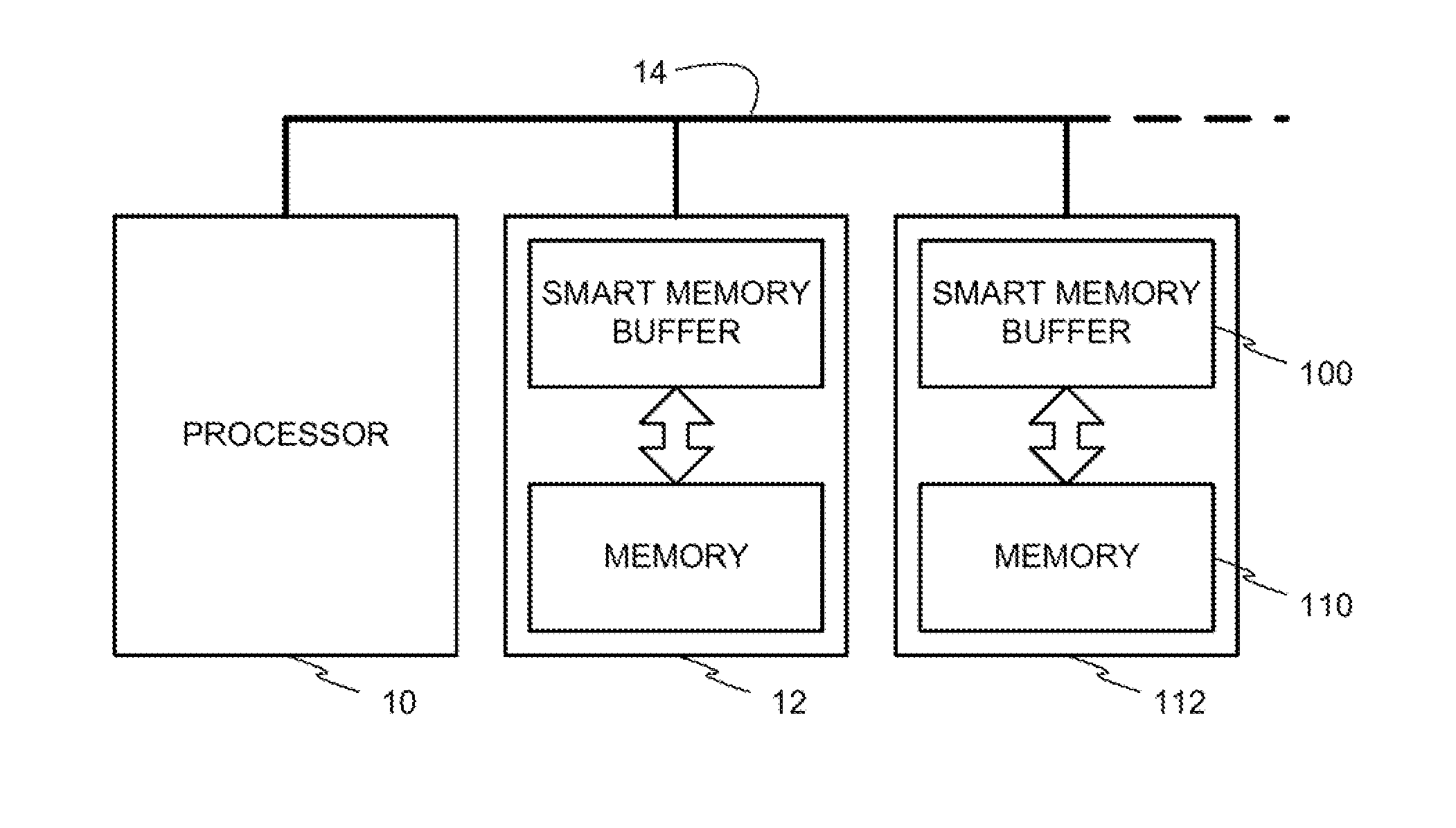
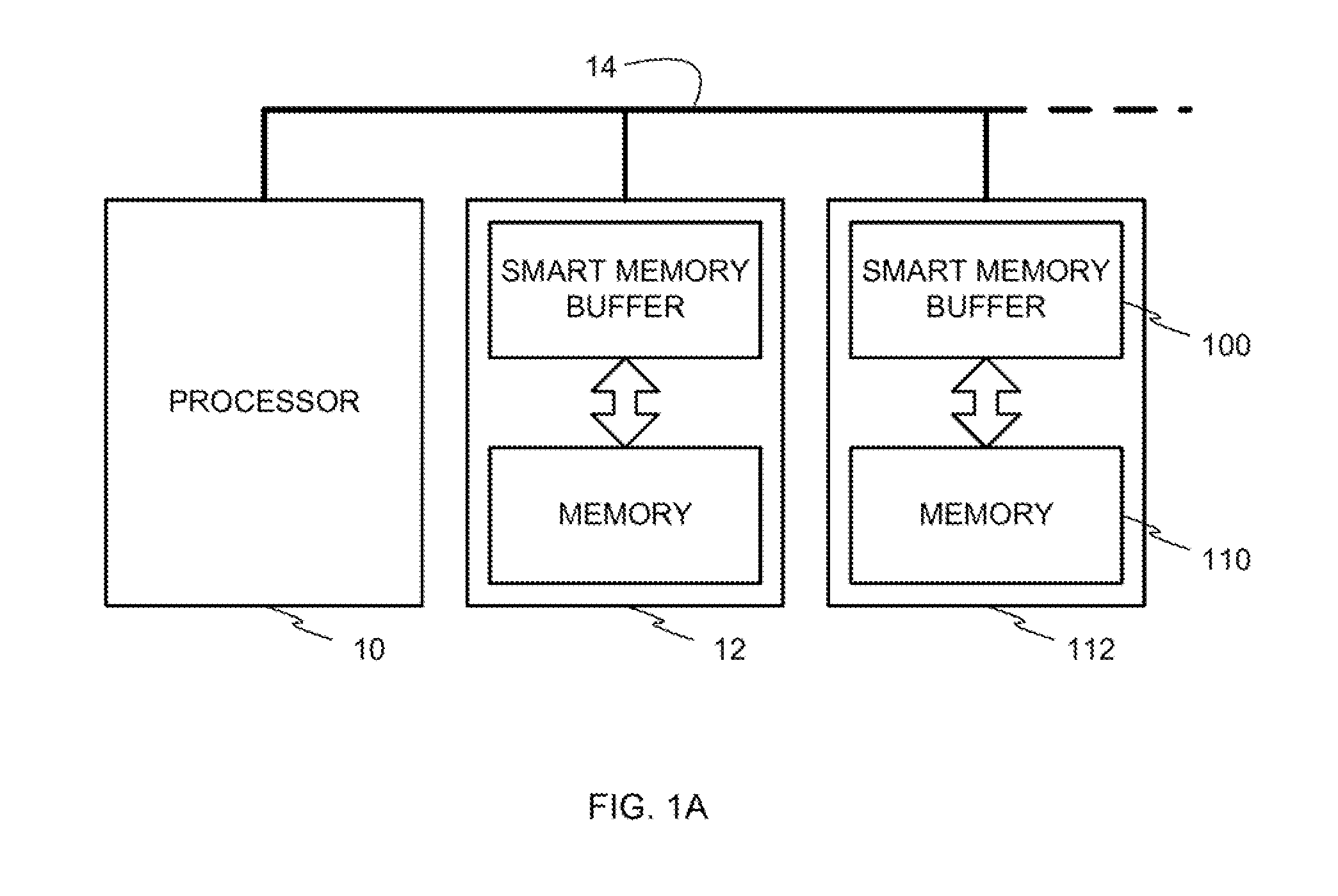
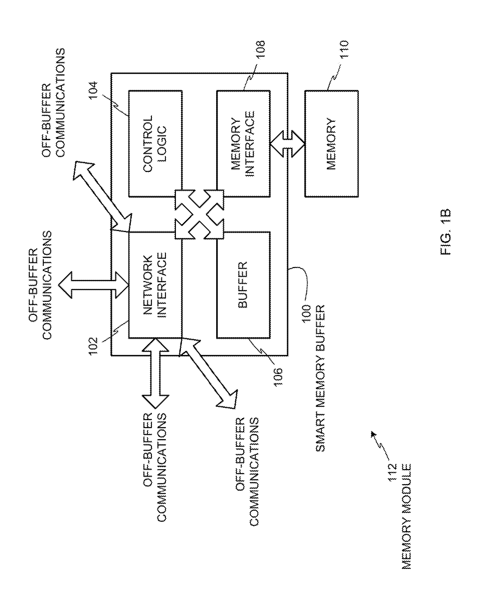
[0015]Example methods, apparatus, and articles of manufacture disclosed herein may be used to implement memory systems using smart memory buffers. Disclosed examples may be used to implement smart memory buffers in memory modules having integrated circuit (IC) or solid state memories. Such memories may be volatile memories such as dynamic random access memory (DRAM) devices or static random access memory devices, and / or non-volatile memories such as flash devices. Memristor devices, etc. Disclosed example smart memory buffers include a memory controller and intelligent functionality to enable memory modules to perform processes in an autonomous manner without requiring the relatively higher levels of intervention by external processors or devices (e.g., memory controllers) required by prior memory systems. In this manner, disclosed example smart memory buffers enable performing memory operations more efficiently by requiring less external communications with processors and / or memory...


PUM


Abstract

An example method involves receiving, at a first memory node, data to be written at a memory location in the first memory node. The data is received from a device. At the first memory node, old data is read from the memory location, without sending the old data to the device. The data is written to the memory location. The data and the old data are sent from the first memory node to a second memory node to store parity information in the second memory node without the device determining the parity information. The parity information is based on the data stored in the first memory node.

Description

STATEMENT OF GOVERNMENT INTEREST[0001]An invention disclosed herein has been made with government support under Contract No. DE-SC0005026, awarded by The Department of Energy. The government has certain rights in the invention.BACKGROUND[0002]Some computing systems use random access memory (RAM) devices as intermediary storage for relatively fast access to data that is also stored in long-term electro-mechanical or electro-optical mass storage devices (e.g., magnetic memories, optical memories, etc.). In this manner, computing systems can perform faster data accesses by copying data from the long-term mass storage devices to the intermediary RAM devices, and accessing the data from the RAM devices.[0003]Long-term solid-state memory devices include non-volatile random access memory (NVRAM) such as phase-change ram (PCRAM), Memristors, and spin-transfer torque random access memory (STT-RAM). An advantage of NVRAM devices over traditional dynamic random access memory (DRAM) is that NVR...

Claims


Application Information

Patent Timeline
Patent Type & Authority Applications(United States)
IPC IPC(8): G06F3/06
CPCG06F3/0619G06F3/0688G06F3/0689G06F3/065G06F3/0665G06F3/0655G06F11/108G06F3/0656G06F2211/1054G06F2211/1066G06F13/16
Inventor YOON, DOE HYUNMURALI-MANOHAR, NAVEENCHANG, JICHUANRANGANATHAN, PARTHASARATHY
Owner HEWLETT-PACKARD ENTERPRISE DEV LP
Why Eureka
Try Eureka