
System and method based on hybrid biometric detection

a biometric detection and hybrid technology, applied in the field of systems and methods based on hybrid biometric detection, can solve the problems of inability to recognize veins, significant influence on vein recognition by physical conditions, and accuracy of face recognition, so as to improve recognition accuracy, lower false acceptance rate, and improve the effect of detection accuracy

Active Publication Date: 2015-07-09
PIXART IMAGING INC
View PDF17 Cites 74 Cited by
  • Summary
  • Abstract
  • Description
  • Claims
  • Application Information

AI Technical Summary

Benefits of technology

The present invention is about a biometric system and method that aims to provide better operational convenience and high recognition accuracy. By using a hybrid recognition approach, the system achieves higher recognition accuracy, lower false acceptance rate, and lower false rejection rate. Additionally, this system offers higher flexibility in terms of the criteria used for identity recognition.

Problems solved by technology

However, vein recognition is significantly affected by physical conditions of human body.
For example, in cold days, veins may contract and become too thin to be sampled, and venous diseases may also cause vein recognition to be impossible.
However, the captured sample for comparison tends to be interfered by facial expressions, ambient light, hair styles and so on, and is not distinguished between twins, and thus the accuracy of face recognition is an issue to be specially considered.
To any biometric system, there is always a tradeoff between comparative performance and tolerance.
If tolerance is decreased for preventing unauthorized users from access (high FAR), it is difficult for authorized users to pass examination (low FRR).
Therefore, existing biometric systems are less flexible and very hard to balance operational convenience and high recognition rate.

Method used


Image

  • System and method based on hybrid biometric detection
  • System and method based on hybrid biometric detection
  • System and method based on hybrid biometric detection

Examples


Embodiment Construction

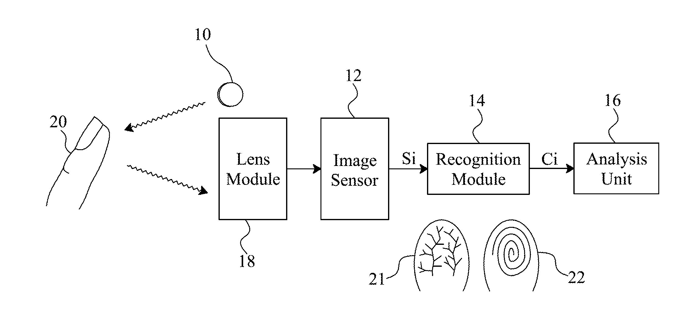
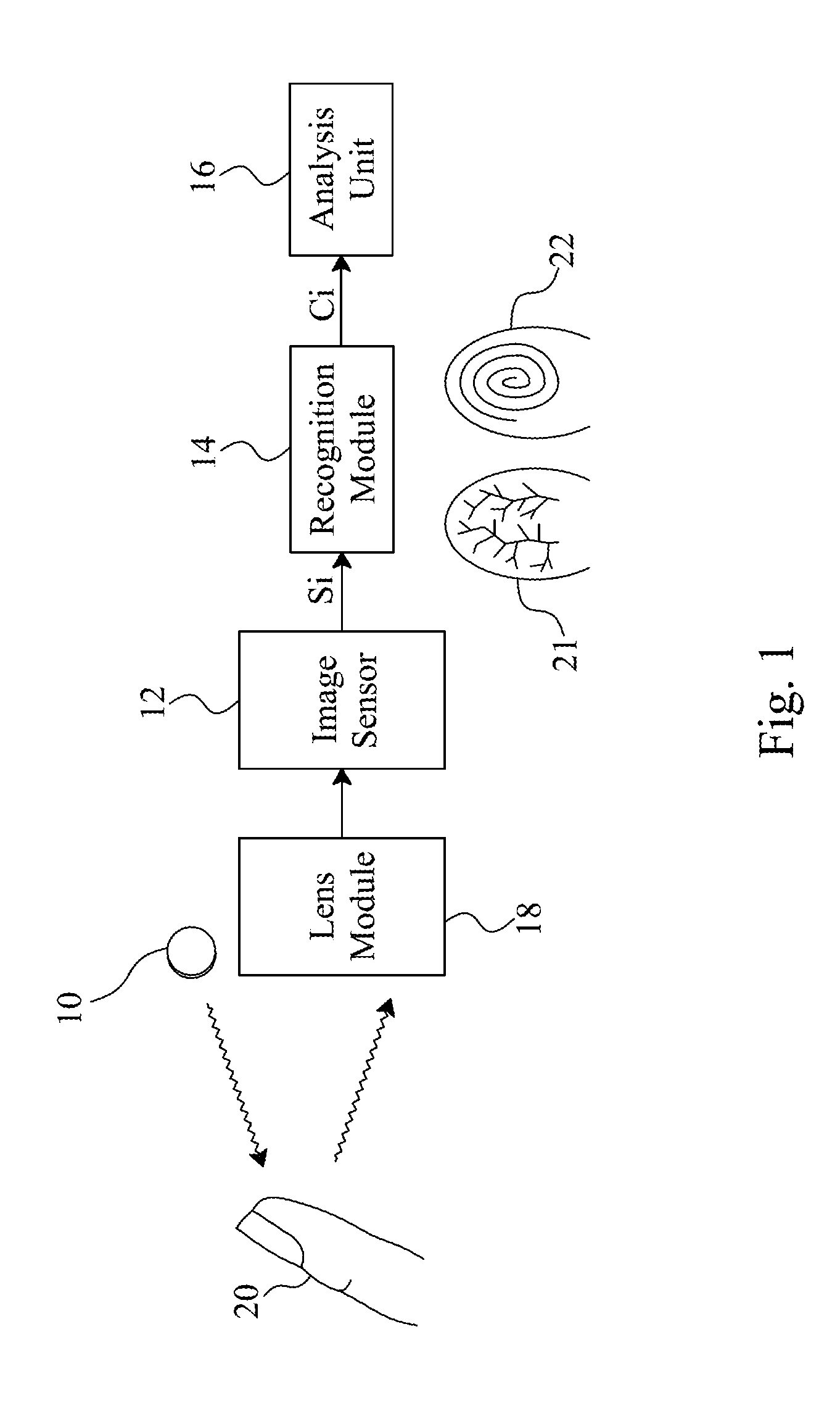
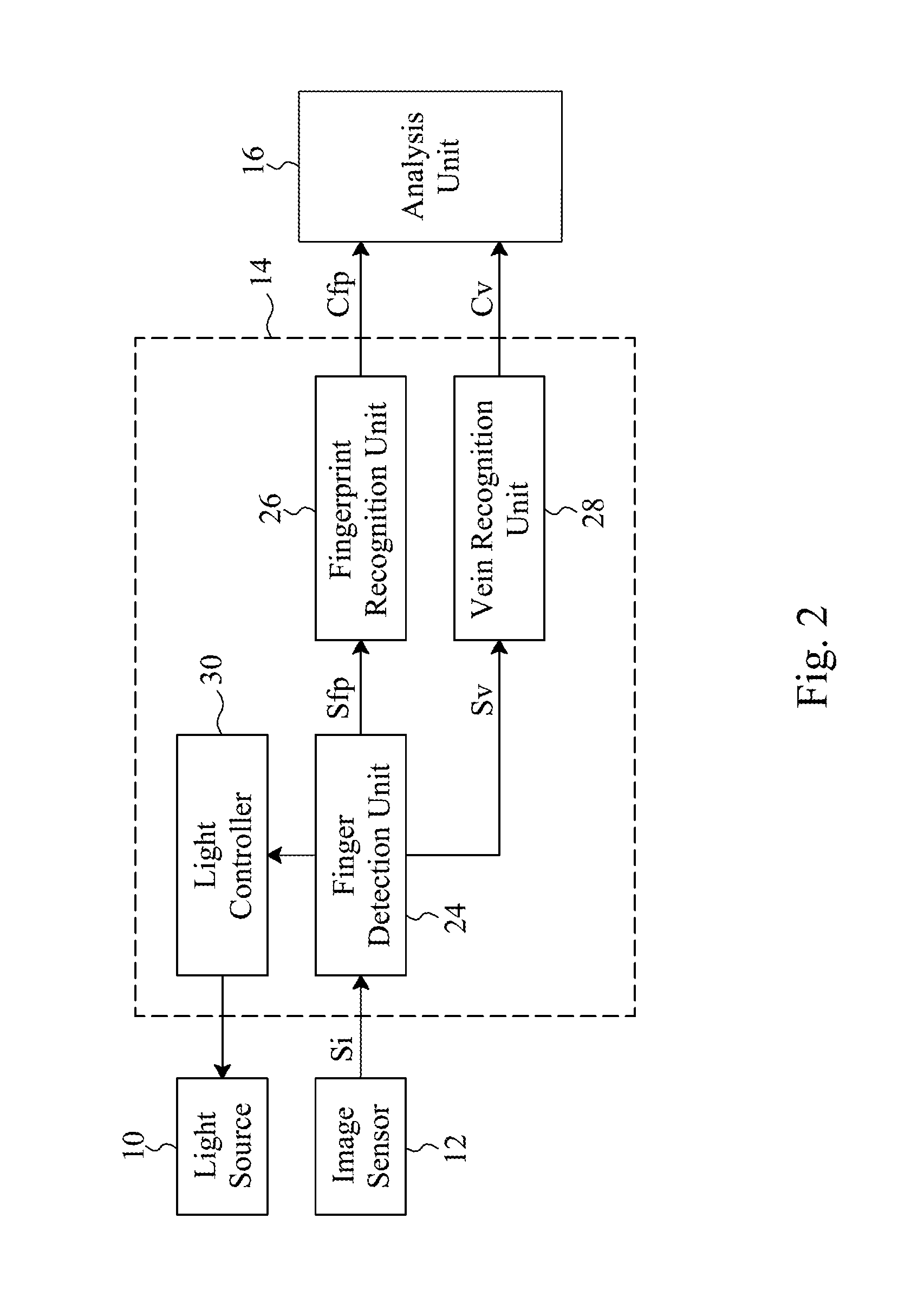
[0018]In an embodiment according to the present invention, referring to FIG. 1, an identity recognition system includes a light source 10 configured to provide light of different wavelengths under control to project on a finger 20, an image sensor 12 configured to capture an image of the finger 20 to generate an image signal Si, a recognition module 14 configured to receive the image signal Si and extract various biometric informations from the received image, analyze and compare for each of the biometric informations to generate a matching score Ci, and an analysis unit 16 configured to determine an identity for the user under recognition according to all of the matching scores Ci. For obtaining better quality images, an autofocus lens module 18 may be provided between the image sensor 12 and the finger 20 for adjusting a focal length according to the location of the finger 20.

[0019]As shown in FIG. 1, various biometric informations are extracted from an image of the finger 20 for ...


PUM


Abstract

A system and method based on hybrid biometric detection capture first images of a user that is projected by first light of different wavelengths, extract various biometric informations from the first images, analyze and compare for each of the biometric informations to generate a matching score, determine an identity for the user according to all of the matching scores, generate second images and PPG signals from dispensed second light from the user, generate a time and PPG variation signal and a space and PPG variation signal for each frame of the second images, convert the time and PPG variation signals into frequency domain signals, determine a reference frequency according to the space and PPG variation signals, retrieve energy of the frequency domain signals at the reference frequency, and establish a three-dimensional energy distribution from the retrieved energy.

Description

CROSS-REFERENCE TO RELATED APPLICATIONS[0001]This application is a continuation-in-part of U.S. patent application Ser. No. 13 / 683,657 entitled “Identity Recognition System And Method Based On Hybrid Biometrics,” filed on Nov. 21, 2012, now co-pending, which claims foreign priority from Taiwan Patent Application No. 100142604, filed on Nov. 21, 2011, the entire contents of each of which are incorporated herein by reference.FIELD OF THE INVENTION[0002]The present invention is related to a system and method based on hybrid biometric detection.BACKGROUND OF THE INVENTION[0003]Biometrics is used for identity recognition, which is based on individual unique biometric information such as fingerprint, face, veins, iris, and retinas. Fingerprint recognition has been extensively used and also become a useful tool for criminal investigation, but fingerprints are relatively easy to duplicate. Vein recognition relies on vein features extracted from the vein distribution in human hands, and thus...

Claims


Application Information

Patent Timeline
IPC IPC(8): G06K9/46G06K9/62H04N7/18G06K9/00G06V40/145
CPCG06K9/46G06K9/00013H04N7/18G06K9/00604G06K9/6201G06T2207/30076G06V40/70G06V40/14G06V40/145G06V40/19G06F18/22
Inventor GU, REN-HAUKAO, MING-TSANHUANG, SEN-HUANG
Owner PIXART IMAGING INC
Learn More