
Solar hybrid photovoltaic-thermal collector assembly and method of use

a photovoltaic and thermal collector technology, applied in the direction of solar heat collector details, thermal-pv hybrid energy generation, lighting and heating apparatus, etc., can solve the problems of mechanical failure, complex conventional solar hybrid energy system, and difficult installation and proper device functioning,

Active Publication Date: 2015-07-09
WILLIAMS DOUGLAS
View PDF14 Cites 21 Cited by
  • Summary
  • Abstract
  • Description
  • Claims
  • Application Information

AI Technical Summary

Benefits of technology

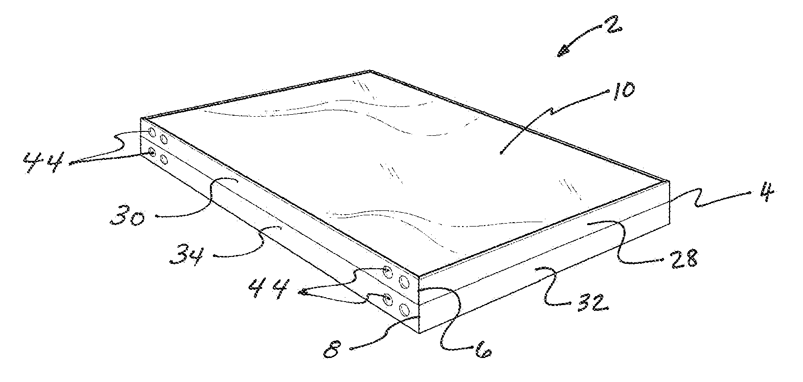
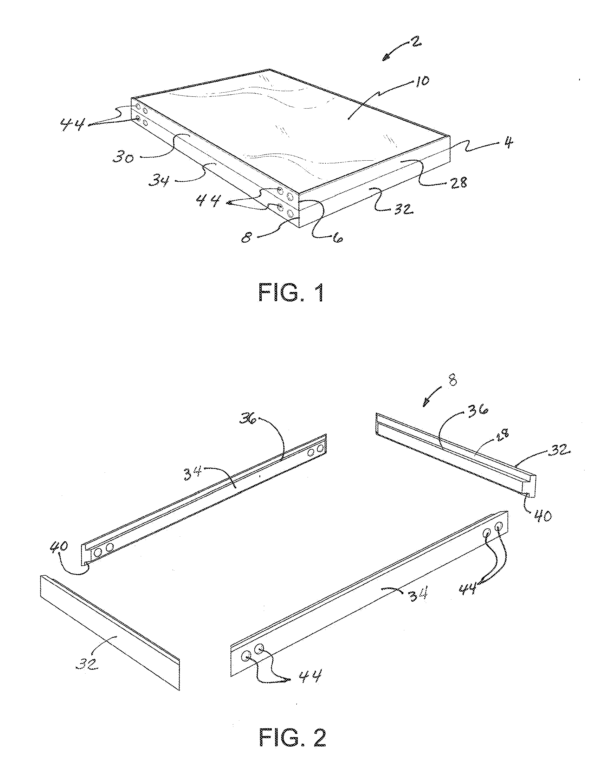
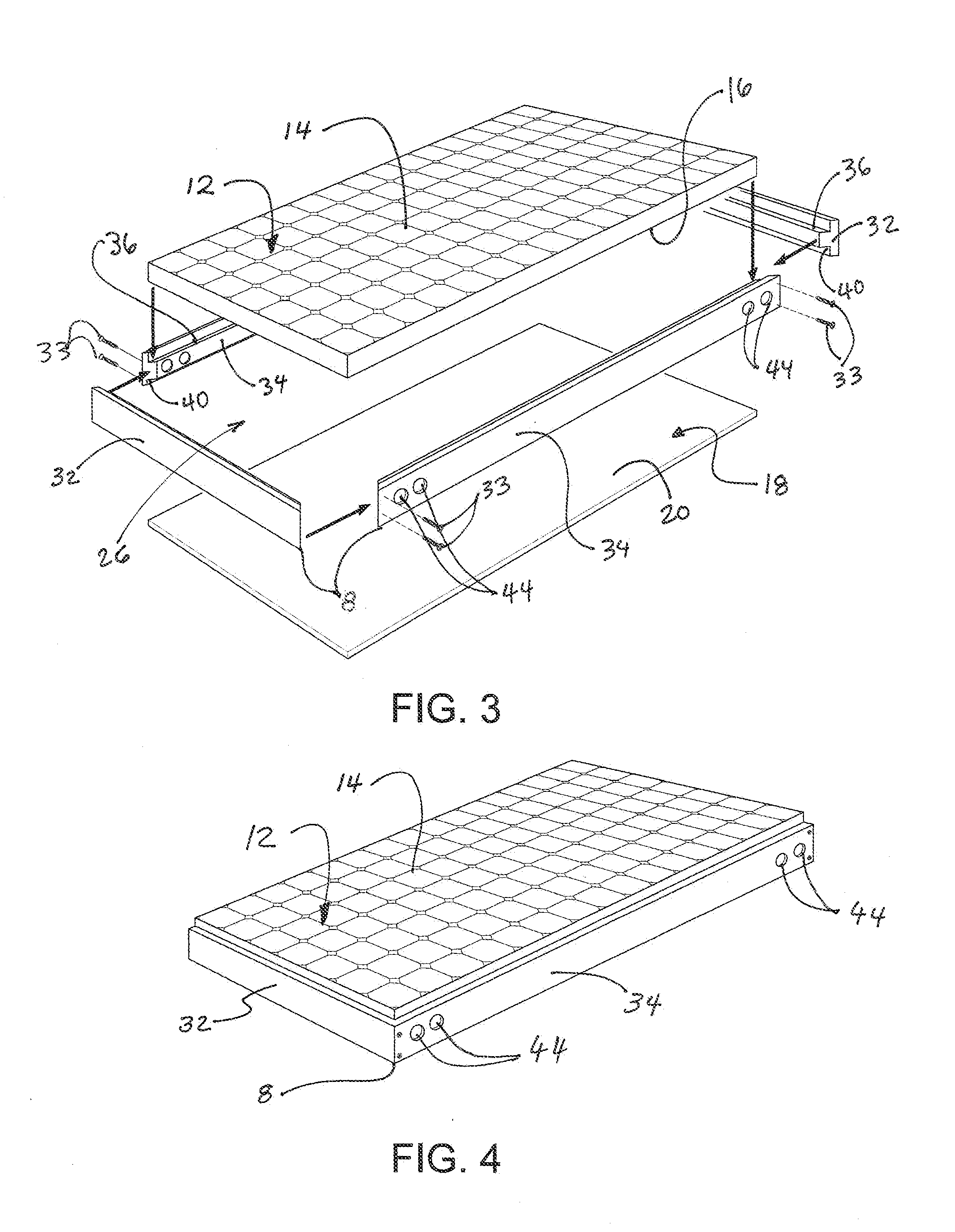
The present invention is about a solar collector assembly that includes a photovoltaic panel and a frame for enclosing the panel. The assembly also includes one or more gas-filled chambers that function as a heat exchange fluid and collect heat from solar energy and / or heat generated by the panel. The gas-filled chambers are positioned on the frame and may be sealed to the panel. The assembly may also include ambient and heated gas conduits for transporting gas to and from the chambers. The technical effects of the invention include improved heat exchange efficiency, reduced energy waste, and improved overall performance of solar collector assemblies.

Problems solved by technology

In addition, the thermal energy collected by a PVT device—energy that would otherwise have been wasted in a PV-only system—may be used constructively in applications including but not limited to water-heating, space-heating, low-temperature generation of electricity, and / or the like.
Notwithstanding the above-described benefits of PVT devices, conventional solar hybrid energy systems remain complex, expensive to manufacture, prone to mechanical failure, and typically require trained and specialized personnel for their installation.
One reason is that the use of liquids (e.g., water, halocarbon coolants, etc.) to cover PV cells and act as heat transfer agents in conventional PVT devices creates challenges for both installation and proper device functioning.

Method used


Image

  • Solar hybrid photovoltaic-thermal collector assembly and method of use
  • Solar hybrid photovoltaic-thermal collector assembly and method of use
  • Solar hybrid photovoltaic-thermal collector assembly and method of use

Examples


Embodiment Construction

[0050]Solar hybrid photovoltaic-thermal (PVT) collectors configured to generate electrical energy from solar energy with associated collection of thermal energy, and to use gas as a heat exchange fluid for transportation of the thermal energy, have been discovered and are described herein. The solar hybrid PVT collectors may be configured to incorporate standard, commercially available photovoltaic (PV) panels.

[0051]In one example, a solar collector assembly in accordance with the present teachings includes (a) a photovoltaic panel having a first side and a second side; (b) a frame configured for enclosing at least a portion of the photovoltaic panel along a periphery thereof; and (c) a first gas-filled chamber provided on the first side of the photovoltaic panel. The first gas-filled chamber is at least partially defined by at least a portion of the frame and by at least a portion of the first side of the photovoltaic panel. Gases such as air (comprised of mostly nitrogen and oxyge...


PUM


Abstract

A solar collector assembly includes a photovoltaic panel having first and second sides, a frame, and a first gas-filled chamber on the first side of the photovoltaic panel. The first gas-filled chamber is at least partially defined by a portion of the frame and by a portion of the first side of the photovoltaic panel. A gas functions as a heat exchange fluid and collects heat from solar energy and / or heat generated by the photovoltaic panel. The photovoltaic panel accumulates and converts solar energy to electrical energy. The solar collector assembly may include a second gas-filled chamber provided on the second side of the photovoltaic panel. The second gas-filled chamber is at least partially defined by a portion of the frame and by a portion of the second side of the photovoltaic panel. Solar collector systems and methods of generating electrical energy and / or thermal energy are also described.

Description

RELATED APPLICATION[0001]This application claims the priority benefit of U.S. Provisional Application No. 61 / 789,541, filed Mar. 15, 2013. The entire contents of the provisional application are incorporated herein by reference, except that in the event of any inconsistent disclosure or definition from the present specification, the disclosure or definition herein shall be deemed to prevail.BACKGROUND OF THE INVENTION[0002]1. Technical Field[0003]The present teachings relate generally to solar energy collection assemblies and, more particularly, to hybrid photovoltaic-thermal collection assemblies.[0004]2. Description of Related Art[0005]Solar hybrid energy collectors, also known as photovoltaic-thermal (PVT) collectors, represent a new and growing field of energy generation. The combination of photovoltaic (PV) and thermal collection in a single unit provides a more efficient collection system than a collector that captures only electrical or only thermal energy. For example, conven...

Claims


Application Information

Patent Timeline
Patent Type & Authority Applications(United States)
IPC IPC(8): H01L31/0525
CPCH01L31/058F24S10/50F24S25/20F24S25/35F24S25/613F24S80/00F24S80/30F24S90/00F24S2020/17F24S10/00H02S30/10H02S40/425H02S40/44Y02B10/10Y02B10/20Y02B10/70Y02E10/44Y02E10/47Y02E10/50Y02E10/60H01L31/052H01L31/0521H01L31/0525H02S20/00H02S40/40H02S40/42
Inventor WILLIAMS, DOUGLAS
Owner WILLIAMS DOUGLAS
Learn More