
Post Driver Having Reverse Twisted Spring Assembly

a technology of reverse twisted springs and post drivers, which is applied in the direction of manufacturing tools, percussive tools, portable drilling machines, etc., can solve the problems of post driver malfunction, spring deterioration or fracture, needing to be removed, etc., and achieves convenient use, less maintenance, and high reliability.

Active Publication Date: 2015-07-16
WORKSAVER
View PDF33 Cites 7 Cited by
  • Summary
  • Abstract
  • Description
  • Claims
  • Application Information

AI Technical Summary

Benefits of technology

The present invention provides a post driver with a reverse twisted spring assembly that has various technical benefits such as being easy to operate, highly reliable, requiring less maintenance, and incorporating a reverse twisted spring inside another spring to reduce vibration. Additionally, the spring assembly may be easily removed for repair or replacement.

Problems solved by technology

The springs used in post drivers are subject to great vibrational forces over time.
Due to these great forces, the springs deteriorate or fracture and need to be removed from the post driver and replaced.
If the springs are not changed in time, then this could lead to malfunctioning of the post driver.
Furthermore, a broken spring, or parts thereof, could get caught between the carriage and the ram, and could lead towards malfunctioning of the driver.
Such could further cause a breakdown in the components, which may be hazardous to an operator or anyone in the vicinity nearby.
Also, when the springs need to be replaced, the post driver is taken out of operation until the repair is completed.
The time that the post driver is down for repair is lost and this leads to a delay in constructing a fence.

Method used


Image

  • Post Driver Having Reverse Twisted Spring Assembly
  • Post Driver Having Reverse Twisted Spring Assembly
  • Post Driver Having Reverse Twisted Spring Assembly

Examples


Embodiment Construction

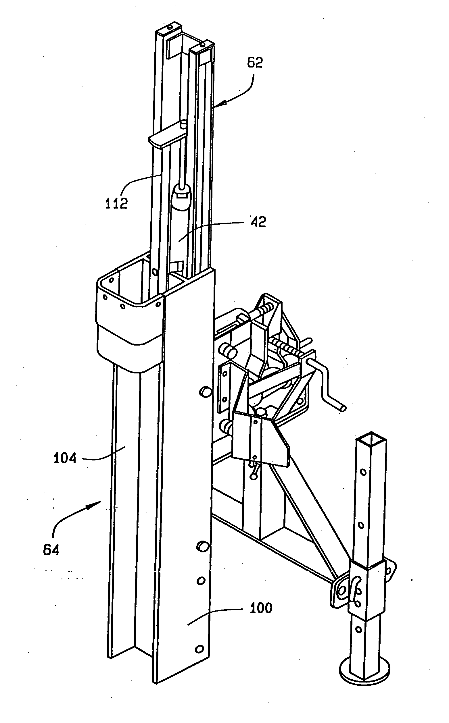
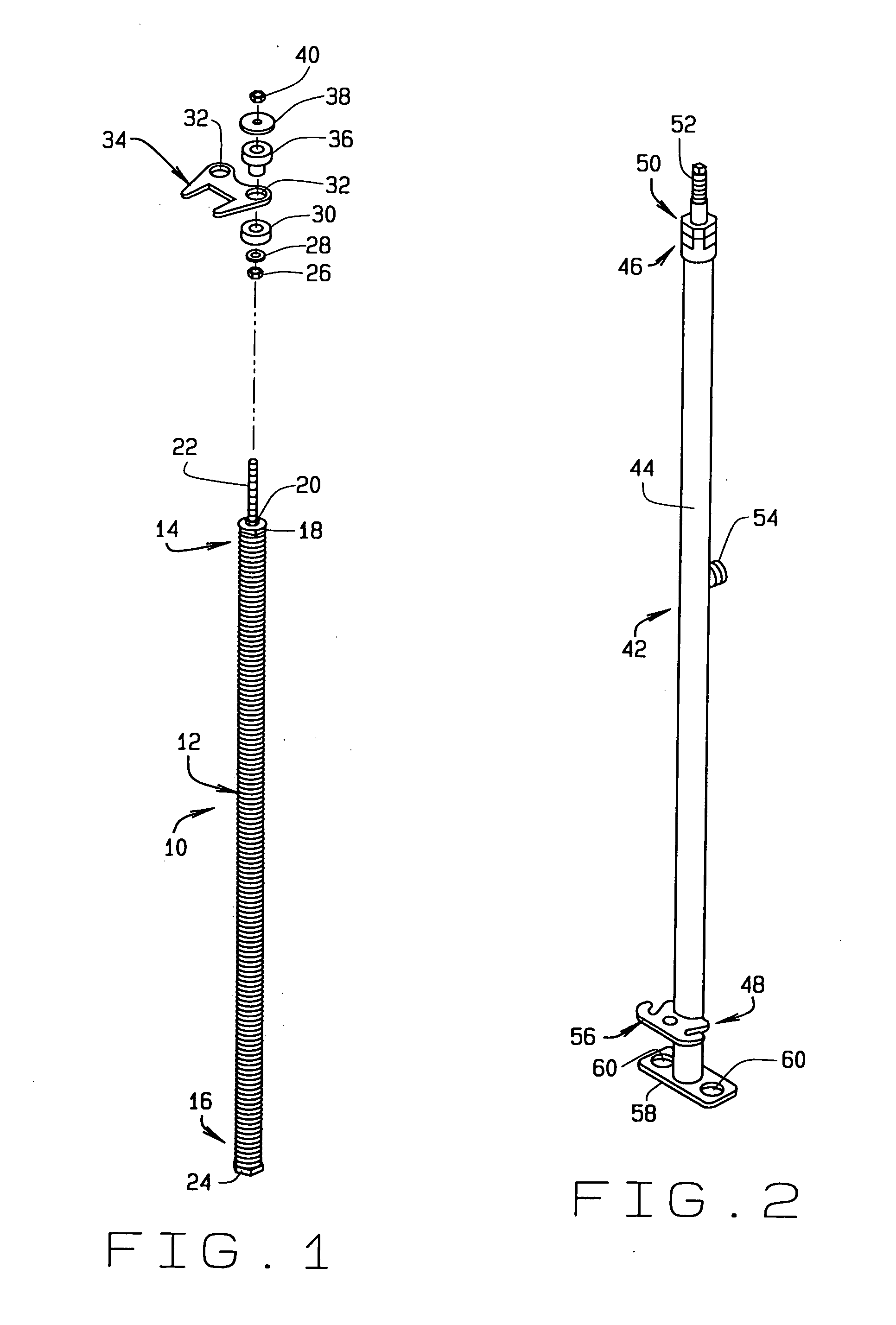
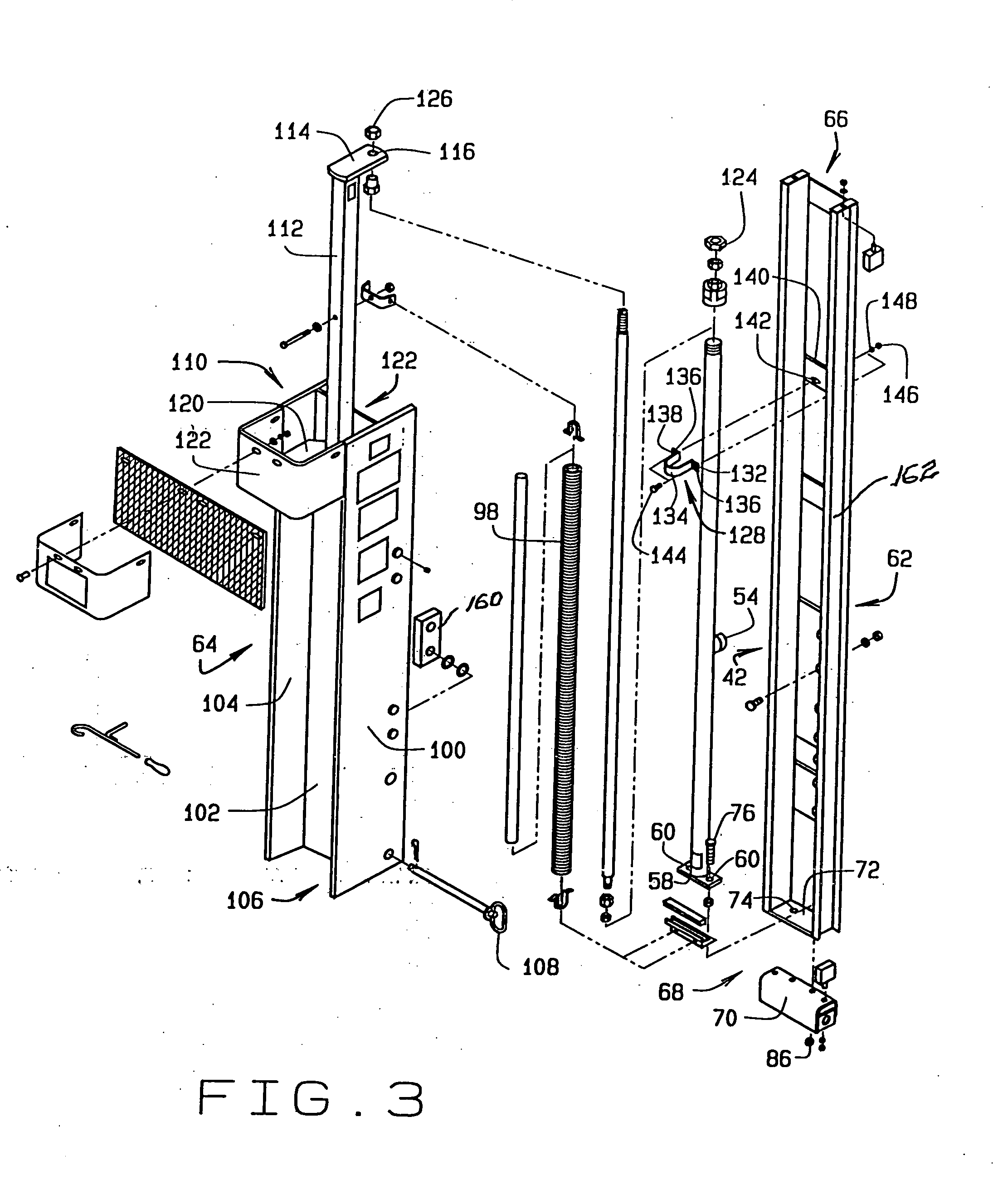
[0023]Referring now to the drawings, wherein like numbers refer to like items, number 10 identifies a spring assembly constructed according to the present disclosure. With reference now to FIG. 1, the spring assembly 10 is shown comprising an outer spring 12 having an upper end 14 and a lower end 16. The upper end 14 has an upper screw-in plug 18, a nut 20, and a threaded rod 22 extending out from the nut 20. The lower end 16 has a lower screw-in plug 24. The rod 22 is inserted into a lower nut 26, a lower washer 28, and a lower grommet 30, one of a pair of apertures 32 formed in an upper bracket 34, an upper grommet 36, an upper washer 38, and an upper nut 40. Although not shown in this particular view, a reverse twisted spring or a reverse spiral spring is inserted into the outer spring 12.

[0024]FIG. 2 shows a hydraulic cylinder assembly 42 that has an outer tube 44, an upper end 46, and a lower end 48. The upper end 46 has end cap assembly 50 having a rod seal (not shown) therein...


PUM

PropertyMeasurementUnit
poweraaaaaaaaaa
electricalaaaaaaaaaa
mechanical energyaaaaaaaaaa

Abstract

A post driver having a reverse twisted spring is disclosed which comprises a carriage, a driving ram which is movable relative to the carriage, a hydraulic cylinder assembly having a threaded hydraulic cylinder rod extending out of a first end of the hydraulic cylinder assembly, the threaded hydraulic cylinder rod capable of movement out of the hydraulic cylinder assembly and retracted back into the hydraulic cylinder assembly, the threaded hydraulic cylinder rod being connected to the driving ram, the hydraulic cylinder assembly having a second end being connected to the carriage, and a spring assembly comprising an outer spring and a reverse twisted spring within the outer spring, a first end having a screw-in plug, a threaded rod extending out of the screw-in plug in the first end with the threaded rod being connected to the driving ram, and a second end connected to the hydraulic cylinder assembly.

Description

CROSS REFERENCE TO RELATED APPLICATION[0001]This non-provisional patent application claims priority to the provisional patent application having Ser. No. 61 / 964,762, filed on Jan. 13, 2014.FIELD OF THE INVENTION[0002]This disclosure generally relates to a post driver device, and more particularly to a post driver having a reverse spiral spring or a reverse twisted spring assembly for reducing vibration, and thereby extending the useful life of the driver.BACKGROUND OF THE INVENTION[0003]Devices, such as hydraulic post drivers have been developed to automate the placement of posts into the ground. Many of these post drivers include a mounting bracket so that the post driver may be connected to a vehicle such as a tractor, a pickup truck, or a skid loader by a three-point hitch. Generally, the post driver draws power from the vehicle to which it is attached. The post driver may be powered by hydraulic, electrical, or mechanical energy. The post driver also has a driving ram that recip...

Claims


Application Information

Patent Timeline
Patent Type & Authority Applications(United States)
IPC IPC(8): E04H17/26F16F3/06
CPCF16F3/06E04H17/263F16F1/125
Inventor BURENGA, THOMAS I.BURENGA, TIM
Owner WORKSAVER
Learn More