Systems and methods for determining the integrity of a vehicle fuel system

Active Publication Date: 2015-07-16
FORD GLOBAL TECH LLC
View PDF7 Cites 13 Cited by
  • Summary
  • Abstract
  • Description
  • Claims
  • Application Information

AI Technical Summary

Benefits of technology

[0004]The inventors herein have recognized these problems, and have developed systems and methods to at least partially address them. In one example a method, comprising: indicating a leak of a first diameter on a canister side of a fuel system following applying a vacuum to the fuel system with a fuel tank isolation valve closed; and indicating a leak of a second diameter on a fuel tank side of the fuel system, based on a vacuum decay in an isolated fuel tank following applying a vacuum to the fuel system with the fuel tank isolation valve open. In this way, an evaporative leak check module with a single reference orifice may be used to determine leaks of multiple sizes in multiple sectors of a fuel system. This may allow current vehicle production models to meet more stringent emissions regulations in the future.
[0005]In another example, a method for an evaporative emissions system leak test, comprising: determining a reference vacuum threshold; determining a first fuel system pressure by drawing a vacuum on a fuel system with a fuel tank isolation valve closed; indicating a leak of a first diameter based on a comparison of the first fuel system pressure to the reference vacuum threshold; opening the fuel tank isolation valve; drawing a vacuum on a fuel system with the fuel tank isolation valve open; closing the fuel tank isolation valve responsive to a second fuel system pressure reaching the reference vacuum threshold; monitoring a rate of change of a fuel tank vacuum while maintaining the fuel tank isolation valve closed; and indicating a leak based on the rate of change of the fuel tank va

Problems solved by technology

In some vehicles, such as hybrid electric vehicles, the vehicle engine may not run frequently, or may not generate enough vacuum to conduct a leak test.
However, evolving regulations require testing for different size leaks in different sectors of the fuel system

Method used


Image

  • Systems and methods for determining the integrity of a vehicle fuel system
  • Systems and methods for determining the integrity of a vehicle fuel system
  • Systems and methods for determining the integrity of a vehicle fuel system

Examples


Embodiment Construction

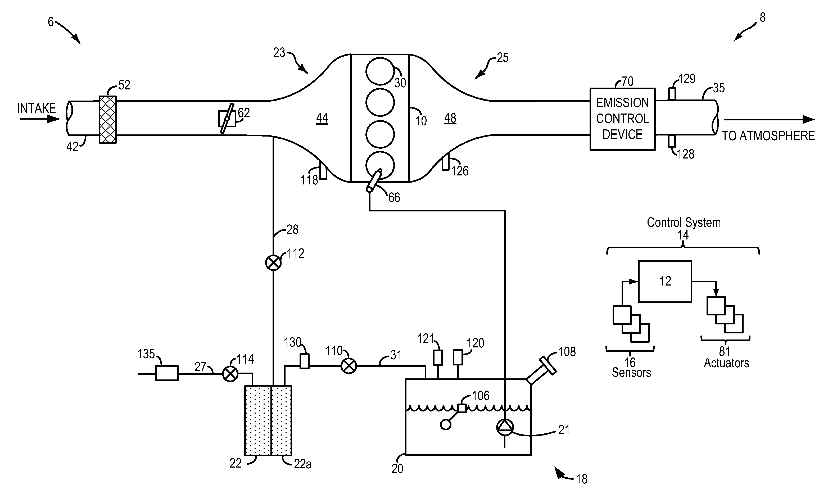
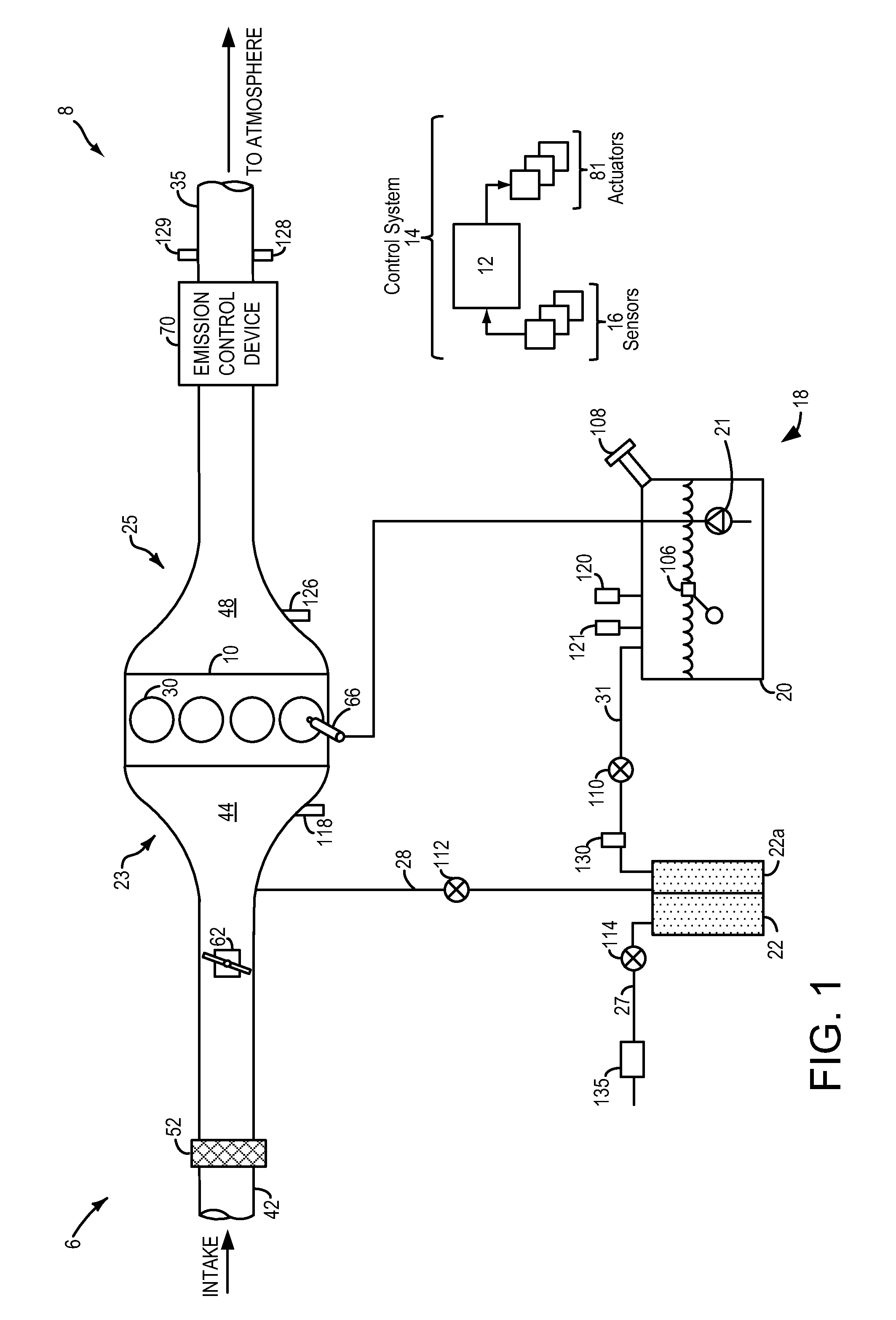
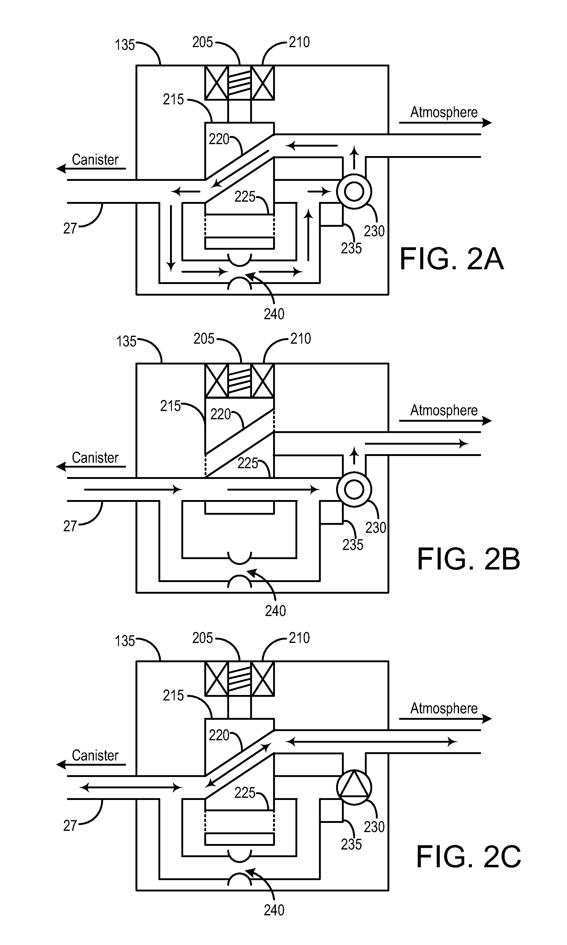
[0018]This description relates to systems and methods for leak testing a fuel system coupled to an engine, such as the fuel system and engine system depicted in FIG. 1. The fuel system and engine system may be included in a hybrid vehicle, and may necessitate the inclusion of an evaporative leak check module (ELCM). An ELCM may be configured to adapt conformations, such as the conformations shown in FIGS. 2A-2C. A controller or power train control module (PCM) may be configured to perform a control routine for an ELCM test, such as the method depicted in FIG. 3. The method may include determining the integrity of the canister side of the fuel system first, followed by determining the integrity of the fuel tank by drawing a vacuum on the fuel tank, sealing the fuel tank, then monitoring the subsequent vacuum bleed-up. FIG. 4 shows an example ELCM test using the method of FIG. 3. FIG. 5 shows an alternative method for determining the integrity of the canister side of the fuel system, ...


PUM


Abstract

A method, comprising: indicating a leak of a first diameter on a canister side of a fuel system following applying a vacuum to the fuel system with a fuel tank isolation valve closed; and indicating a leak of a second diameter on a fuel tank side of the fuel system, based on a vacuum decay in an isolated fuel tank following applying a vacuum to the fuel system with the fuel tank isolation valve open. In this way, an evaporative leak check module with a single reference orifice may be used to determine leaks of multiple sizes in multiple sectors of a fuel system. This may allow current production models to meet more stringent emissions regulations in the future.

Description

BACKGROUND AND SUMMARY[0001]Vehicle emission control systems may be configured to store fuel vapors from fuel tank refueling and diurnal engine operations, and then purge the stored vapors during a subsequent engine operation. In an effort to meet stringent federal emissions regulations, emission control systems may need to be intermittently diagnosed for the presence of leaks that could release fuel vapors to the atmosphere. In a typical leak test, a vacuum is applied to the fuel system. The integrity of the system is determined by monitoring the decay of the applied vacuum or by comparing the resulting fuel system pressure to an expected pressure. The vacuum source may be the intake manifold of the vehicle engine.[0002]In some vehicles, such as hybrid electric vehicles, the vehicle engine may not run frequently, or may not generate enough vacuum to conduct a leak test. Such vehicles are required to have an evaporative leak check module (ELCM) coupled to the fuel system. The ELCM i...

Claims


Application Information

Patent Timeline
IPC IPC(8): F02D41/00
CPCF02D41/0032F02M25/0809F02D29/02
Inventor DUDAR, AED M.YANG, DENNIS SEUNG-MANPEARCE, RUSSELL RANDALL
Owner FORD GLOBAL TECH LLC
Why Eureka
Try Eureka