HVAC control system and method of controlling an HVAC system

a technology of hvac control system and control system, applied in the field of control system, can solve the problems of difficult setting and maintaining rigid timing and scheduling parameters of programmable thermostats, and achieve the effects of reducing the cost of operating the climate control system

Inactive Publication Date: 2015-07-16
VEDPATHAK GIRISH
View PDF4 Cites 47 Cited by
  • Summary
  • Abstract
  • Description
  • Claims
  • Application Information

AI Technical Summary

Benefits of technology

[0009]The disclosure is directed to a thermostat that includes a first communication connection, a second communication connection, a user communication connection, one or more processor units and one or more computer readable media. The first communication connection is in communication with at least one condition sensor. The second communication connection is in communication with a climate control system. The user communication connection is configured to receive an input from a user requesting a change in operating parameters of the thermostat. The one or more processor units is in communication with the first and second communication connections as well as with the user communication connection. The one or more computer-readable media comprising computer-executable instructions which, when executed by the one or more processing units, cause the thermostat to perform steps comprising: receiving a communication from the user communication connection to reduce a cost of operating the climate control system; receiving communication through the first communication connection pertaining to the at least one condition sensor; determining at least one operating parameter of the climate control system to be changed to reduce the cost of operating the climate control system; and communicating through the second communication connection with the climate control system to alter the at least one operating parameter of the climate control system to achieve a reduction in the cost of operating the climate control system.

Problems solved by technology

Problematically, the programmable thermostats were often, and continue to be, difficult to set and provide very rigid timing and scheduling parameters.

Method used


Image

  • HVAC control system and method of controlling an HVAC system
  • HVAC control system and method of controlling an HVAC system
  • HVAC control system and method of controlling an HVAC system

Examples


Embodiment Construction

[0035]While this invention is susceptible of embodiment in many different forms, there is shown in the drawings and described herein in detail a specific embodiment with the understanding that the present disclosure is to be considered as an exemplification and is not intended to be limited to the embodiment illustrated.

[0036]It will be understood that like or analogous elements and / or components, referred to herein, may be identified throughout the drawings by like reference characters. In addition, it will be understood that the drawings are merely schematic representations of the invention, and some of the components may have been distorted from actual scale for purposes of pictorial clarity.

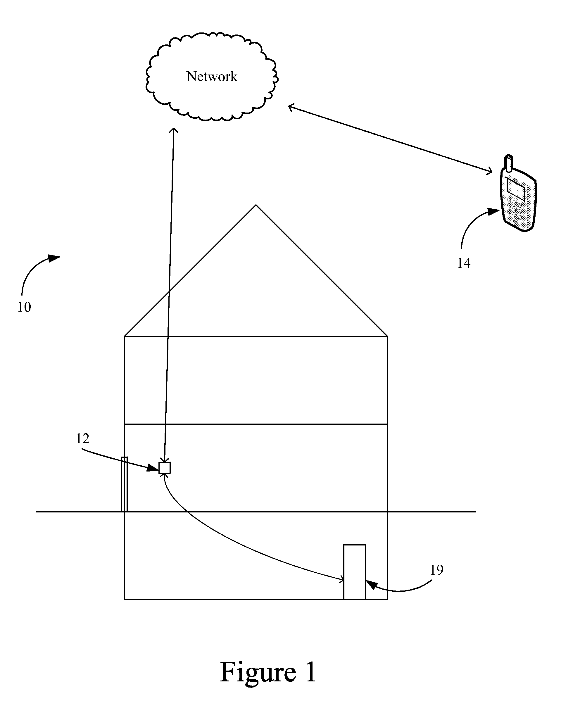
[0037]Referring now to the drawings and in particular to FIG. 1, the HVAC control system (also referred to commonly as a thermostat) is shown generally at 10. The control system can be coupled to heating and / or cooling equipment 19, such as an air conditioner, a heat pump, a furnace and the l...


PUM


Abstract

A control system is configured to improve the efficiency of the heating and/or cooling equipment, and to aid in cutting costs associated with the running of the heating and/or cooling equipment. That is, to save the user on utility costs, while maintaining comfort within the space that is controlled. It is another objective to facilitate advanced programming of the system as well as scheduling conflict resolution. The control system generally comprises a control unit 12 and a remote controller 14 (which may comprise a smartphone, a computer or the like).

Description

CROSS-REFERENCE TO RELATED APPLICATION[0001]This application claims priority from U.S. Provisional Patent Application Ser. No. 61 / 927,689 filed Jan. 15, 2014, entitled “HVAC Control System And Method Of Controlling An HVAC System”, the entire disclosure of which is hereby incorporated by reference in its entirety.BACKGROUND OF THE DISCLOSURE[0002]1. Field of the Disclosure[0003]The disclosure relates in general to a control system, and more particularly, to a HVAC control system which provides savings to the user by meeting the user's climate control needs while maximizing efficiency. It will be understood that HVAC refers to climate control systems generally and interchangeably. It will be understood that HVAC and / or climate control system may include any number of units and types of systems that alter temperature or other conditions in a given space (i.e., air conditioner, heater, heat pump, electric floor heat, swamp cooler, evaporator, among others). The use of HVAC and / or clima...

Claims


Application Information

Patent Timeline
Patent Type & Authority Applications(United States)
IPC IPC(8): F24F11/00G05B15/02
CPCG05B15/02F24F11/006G05B19/0426G05B2219/23051G05B2219/25387G05B2219/2614
Inventor VEDPATHAK, GIRISH
Owner VEDPATHAK GIRISH
Why Eureka
Try Eureka