Method and apparatus for indoor position tagging

a position tagging and indoor technology, applied in the field of localization and mapping, can solve the problems of difficult to efficiently deploy network small cells and analyze network performance, manual labor for performance optimization of indoor network small cells, and inability to provide reliable indoor environment coverage by global positioning systems (gps)

Active Publication Date: 2015-07-16
WSOU INVESTMENTS LLC
View PDF5 Cites 30 Cited by
  • Summary
  • Abstract
  • Description
  • Claims
  • Application Information

AI Technical Summary

Benefits of technology

[0003]According to an embodiment, a system for providing position tagging during the deployment and / or optimization of indoor network small cells within an environment includes at least one mobile electronic device adapted to be moved within the environment and a pedestrian dead reckoning module. The at least one mobile electronic device includes an inertial measurement unit and at least one of a near field communication chip, barcode scanner, global positioning system, Bluetooth receiver or WiFi receiver. The pedestrian dead reckoning module is adapted to query and record time stamped readings from the inertial measurement unit and at least one of the near field communication chip, barcode scanner, global positioning system, Bluetooth receiver or WiFi receiver.

Problems solved by technology

Global positioning systems (GPS) do not typically provide reliable coverage of indoor environments due to GPS signal penetration loss, often estimated to be 20 dB.
Without reliable GPS coverage, GPS end user coordinate information is typically not available in the indoor environments, making it difficult to efficiently deploy network small cells and analyze network performance because the location of User Equipment (UE) within the indoor environment cannot be reliably pinpointed.
Consequently, indoor network small cells are often placed in a subjective manner by equal spatial distribution and performance optimization of indoor network small cells is manual labor intensive.

Method used


Image

  • Method and apparatus for indoor position tagging
  • Method and apparatus for indoor position tagging
  • Method and apparatus for indoor position tagging

Examples


Embodiment Construction

[0030]Before the various embodiments are described in further detail, it is to be understood that the invention is not limited to the particular embodiments described. It will be understood by one of ordinary skill in the art that the systems and methods described herein may be adapted and modified as is appropriate for the application being addressed and that the systems and methods described herein may be employed in other suitable applications, and that such other additions and modifications will not depart from the scope thereof.

[0031]In the drawings, like reference numerals refer to like features of the systems and methods of the present application. Accordingly, although certain descriptions may refer only to certain Figures and reference numerals, it should be understood that such descriptions might be equally applicable to like reference numerals in other Figures.

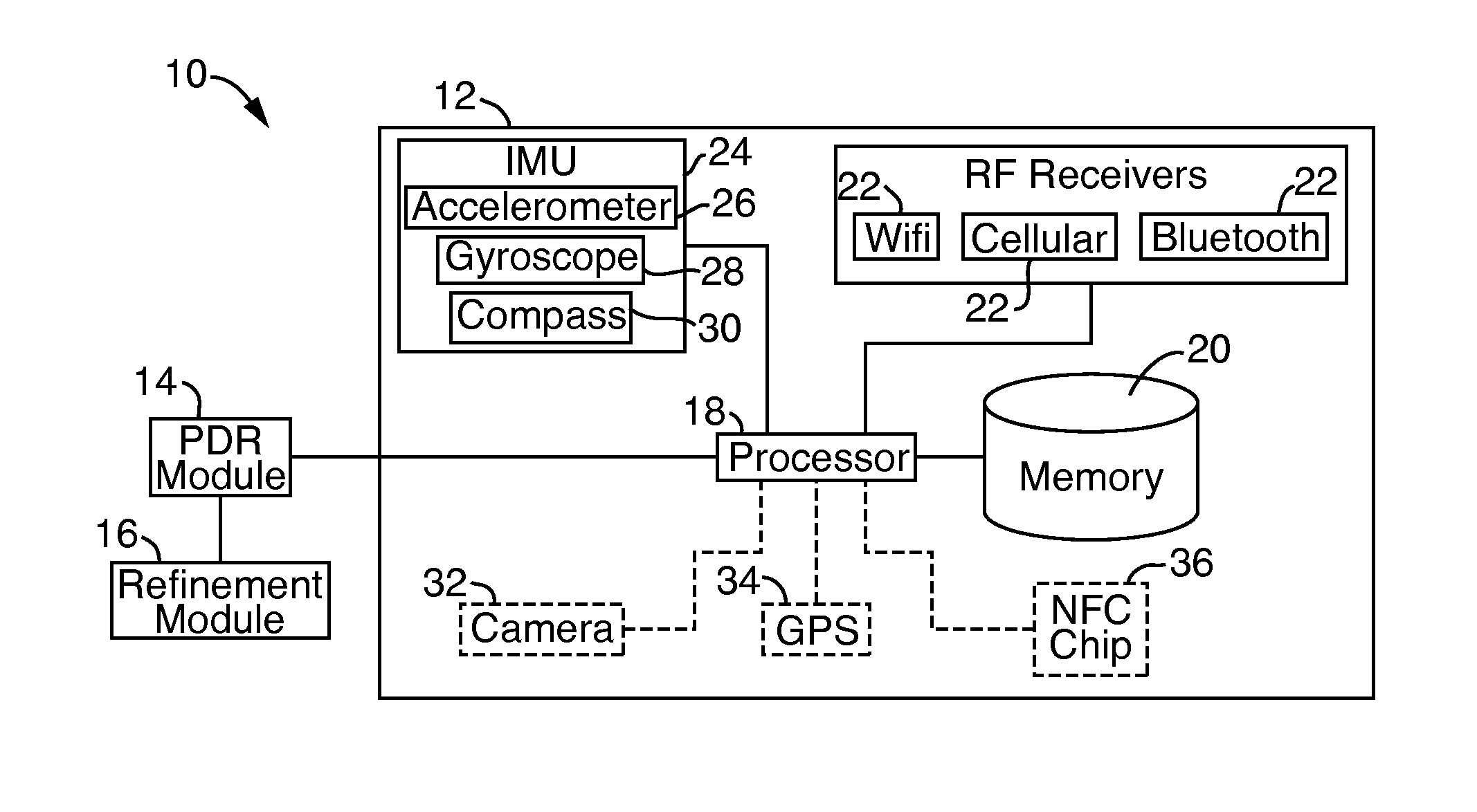
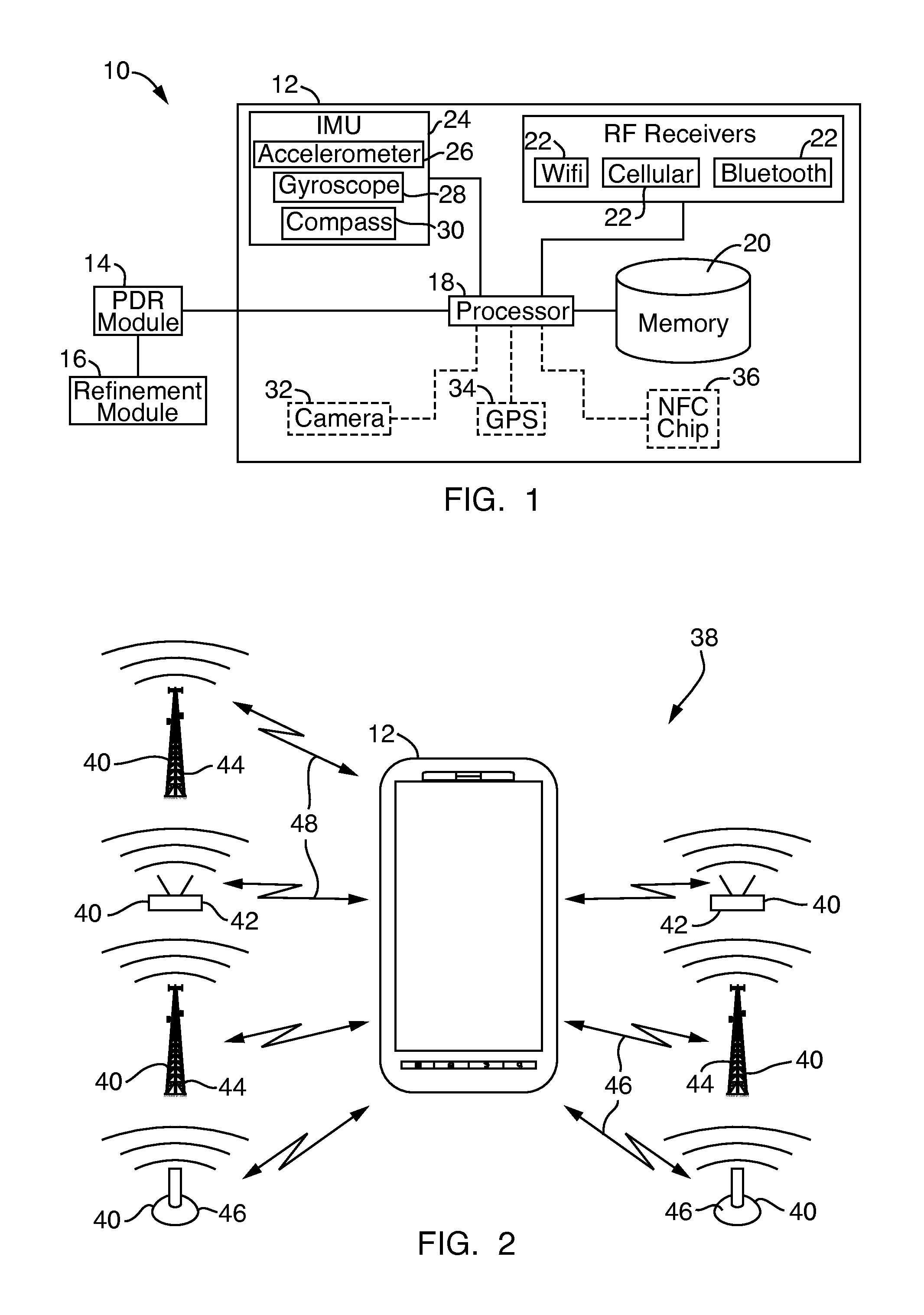
[0032]Referring to FIG. 1, a system 10 for indoor position tagging of user equipment 12 includes a pedestrian dea...


PUM


Abstract

A system and method for position tagging within an environment includes at least one mobile electronic device adapted to be moved within the environment and a pedestrian dead reckoning module. The at least one mobile electronic device includes an inertial measurement unit and at least one of a near field communication chip, barcode scanner, global positioning system, Bluetooth receiver or WiFi receiver. The pedestrian dead reckoning module is adapted to query and record time stamped readings from the inertial measurement unit and the at least one of the near field communication chip, barcode scanner, global positioning system, Bluetooth receiver or WiFi receiver. The system and method may generate one or more spatial maps of the environment through the collection of radio frequency signal data along with the time stamped readings.

Description

FIELD OF THE INVENTION[0001]The present invention relates to localization and mapping.BACKGROUND OF THE INVENTION[0002]Global positioning systems (GPS) do not typically provide reliable coverage of indoor environments due to GPS signal penetration loss, often estimated to be 20 dB. Without reliable GPS coverage, GPS end user coordinate information is typically not available in the indoor environments, making it difficult to efficiently deploy network small cells and analyze network performance because the location of User Equipment (UE) within the indoor environment cannot be reliably pinpointed. Consequently, indoor network small cells are often placed in a subjective manner by equal spatial distribution and performance optimization of indoor network small cells is manual labor intensive.SUMMARY[0003]According to an embodiment, a system for providing position tagging during the deployment and / or optimization of indoor network small cells within an environment includes at least one ...

Claims


Application Information

Patent Timeline
Patent Type & Authority Applications(United States)
IPC IPC(8): G01C21/16
CPCG01C21/16G01C21/206G01S5/02525G01S5/02526G01S19/49H04W16/20
Inventor CHEN, BYRONORTEGA, AMYHO, TINMIROWSKI, PIOTR
Owner WSOU INVESTMENTS LLC
Why Eureka
Try Eureka