Self-test gfci device with dual solenoid coil electric control

a technology of solenoid coil and electric control, which is applied in the direction of circuit-breaking switches, switches with electromagnetic release, emergency protective arrangements for limiting excess voltage/current, etc., can solve the problems of increasing the risk of potentially life-threatening injuries, one or more electronic components that drive the mechanical current interrupting device in a gfci can short-out or otherwise become defective,

Active Publication Date: 2015-07-16
HUBBELL INC
View PDF4 Cites 30 Cited by
  • Summary
  • Abstract
  • Description
  • Claims
  • Application Information

AI Technical Summary

Benefits of technology

[0015]Using two solenoid coils, however, requires additional design considerations. For example, it is not ideal to drive two independent SCRs with a single trigger signal generated by the 4141 chip because each SCR causes inherent feedback during the time when the 4141 chip is firing the trigger signal and driving two SCRs simultaneously causes a combined feedback that can damage the 4141 chip. To avoid this potentially damaging feedback problem a device in accordance with one or more embodiments includes a third SCR that blocks the feedback from the two coil-driving SCRs from reaching the 4141 chip trigger signal output port. Thus, the design requirements for the 4141 chip are satisfied and both coils can still be driven simultaneously. Another advantage of a device consistent with one or more exemplary embodiments, as compared to conventional GFCI devices, is that separate independent firing of the coil-driving SCRs can be performed. That is, according to another aspect of these embodiments, a gate signal from a microcontroller drives the two coil-driving SCRs under certain predetermined conditions while blocking the trigger signal generated by the 4141 chip from interfering with the gate signal.
[0016]An end-of-life indicator is also coupled to the microcontroller to indicate whether the GFCI device has failed to properly detect the test signal or whether some other malfunction within the device has occurred. To avoid tripping the mechanical current-interrupting device when the test signal is generated, but also allow as much of the GFCI device circuitry to perform its intended function, a unique monitor circuit is provided that takes advantage of various functionality of the digital components, such as the GFCI integrated circuit device and the microcontroller. Specifically, to provide an automatic test function that monitors the fault detection capability of the GFCI device without interfering and causing a false trip under normal conditions, embodiments consistent with the invention include a specifically selected filter capacitor associated with the interrupter drive output of the GFCI integrated circuit (IC) device. Proper selection of the capacitor and other related circuit components prevents the interrupter drive circuit, e.g., silicon controlled rectifier (SCR), from firing, or turning ON, until a real fault condition is encountered.

Problems solved by technology

Like most electro-mechanical devices, however, GFCI devices are susceptible to failure.
For example, one or more of the electronic components that drive the mechanical current interrupting device in a GFCI can short-out or otherwise become defective, as can components in the fault detector circuit or elsewhere within the device.
Such component failures can render the device unable to properly detect a ground fault, and / or properly interrupt the flow of electrical current when a fault is detected, thus, increasing the risk of potentially life-threatening injury.
If the device is functioning properly, the simulated ground fault is detected and the device will trip, i.e., the mechanical interrupter is actuated.
This study further revealed that some GFCI devices that had been in service for an extended period of time became non-functional and were unable to properly detect a fault condition, thus, rendering the device unsafe.
Specifically, it was discovered that after extended use GFCI devices fail to trip when a fault occurs, thus rendering the device operable as an electrical receptacle only.
That is, the device would provide electrical power to the load contacts at all times and not be able to trip when a fault condition was present.
Because GFCI devices were not being regularly tested, this unsafe condition became exacerbated.
More particularly, people falsely believed the device was operational, in view of the fact that it was adequately delivering power, when in fact the device was a potentially life-threatening hazard.
The discovery that GFCI devices deployed in the field are becoming increasingly non-operational and unsafe in combination with the realization that people do not regularly test their GFCI devices, regardless of manufacturer's explicit instructions to do so, initiated investigations into possible changes to the UL-943 standard, including changes that would require the GFCI devices to self-test (e.g., auto-monitor) themselves without the need for human intervention.
The digital solutions offered thus far, however, are not ideal.
For example, several related art GFCI designs, including those directed at providing self-test functionality, suffer from nuisance tripping, a situation where the interrupter is actuated when neither a real ground fault, a manually generated simulated ground fault, nor an automatic self-test fault are present.
This unfavorable condition is believed by many to be worsened by the additional requirement of automatic self-testing, which often results in additional inductive currents being generated within the device.

Method used


Image

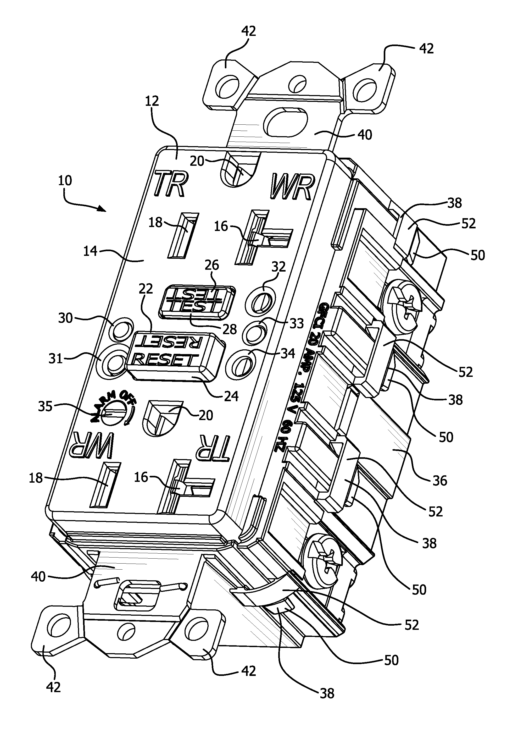
  • Self-test gfci device with dual solenoid coil electric control
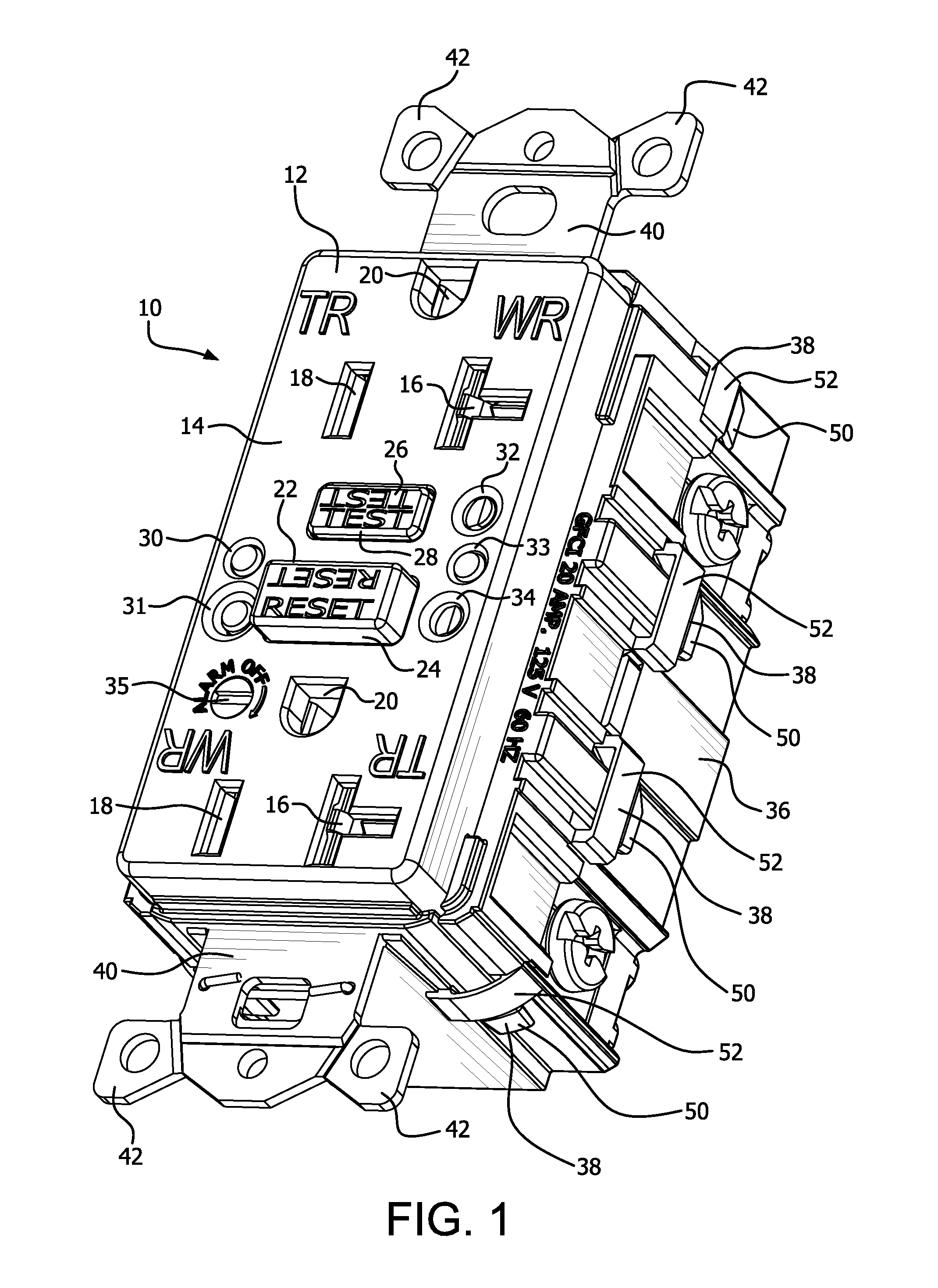
  • Self-test gfci device with dual solenoid coil electric control
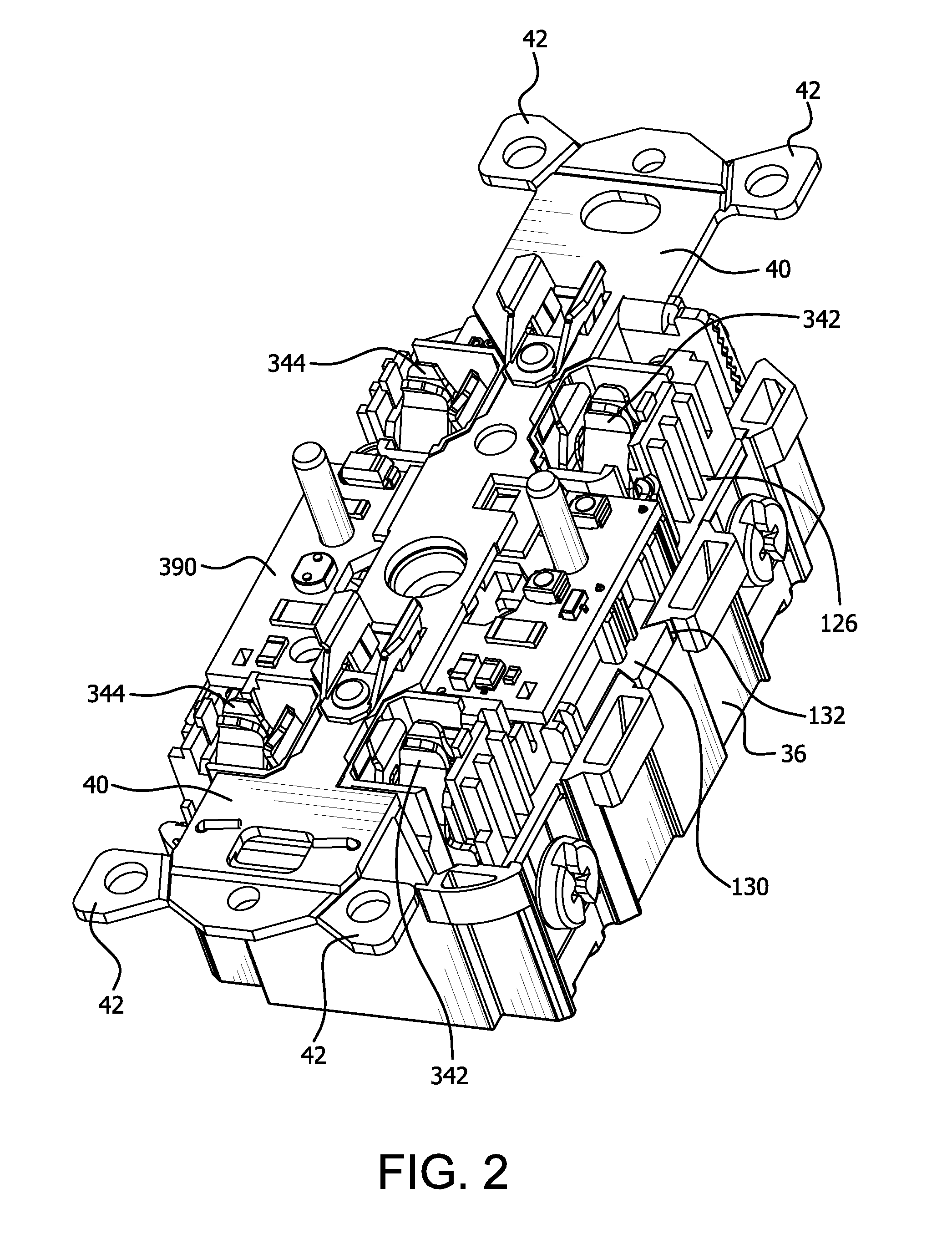
  • Self-test gfci device with dual solenoid coil electric control

Examples


Embodiment Construction

[0013]In consideration of problematic issues associated with related art GFCI devices, including but not limited to the problematic issues discussed above, a circuit in accordance with one or more exemplary embodiments generally relates to an auto-monitoring circuit that continuously monitors the performance of a GFCI device. More specifically, a processing device, such as a microcontroller or microprocessor, is configured to periodically perform an auto-monitoring routine based on a stored software program for testing and verifying the viability and functionality of various sub-circuits within the GFCI device. To test proper current isolation of the GFCI device, a driver coupled to the microcontroller is operated to initiate a test signal representative of a ground fault each time the auto-monitoring routine is performed, or run, and different circuit nodes are monitored to confirm proper operation of the device.

[0014]A GFCI device in accordance with at least one embodiment uses a ...


PUM


Abstract

A circuit interrupting device having a dual-coil solenoid for delivering an increased magnetic field to the solenoid plunger when a fault is detected and it is desired to place the device into a tripped condition. Independent switching devices control the flow of current through the respective coils of the solenoid and a third switching device controls the operation of the two coil driving switch devices. A detection circuit detects faults and controls the third switching device to activate the coil driving switching devices when a fault is detected. A programmable device runs a self-test program to determine whether the device is operating properly and faults can be detected. The programmable device can also independently control the operation of the two coil driving switching devices.

Description

CROSS-REFERENCE TO RELATED APPLICATIONS[0001]This application contains subject matter related to subject matter contained in co-pending U.S. patent application Ser. No. 13 / 827,785, titled, “GFCI TEST MONITOR CIRCUIT,” by Stephen P. Simonin, U.S. patent application Ser. No. 13 / 422,797, titled, “SOLENOID COIL HAVING AN ENHANCED MAGNETIC FIELD,” by Stephen P. Simonin, U.S. patent application Ser. No. 13 / 422,790, titled, “ENHANCED AUTO-MONITORING CIRCUIT AND METHOD FOR AN ELECTRICAL DEVICE,” by Gaetano Bonasia and Kenny Padro and U.S. patent application Ser. No. 13 / 422,793, titled, “REINSTALLABLE CIRCUIT INTERRUPTING DEVICE WITH VIBRATION RESISTANT MISWIRE PROTECTION,” by Gaetano Bonasia et al., the entire contents of each of which are expressly incorporated herein by reference, and each of which is assigned to the same assignee as the instant application.BACKGROUND[0002]1. Field[0003]The present disclosure relates generally to switched electrical devices. More particularly, the disclos...

Claims


Application Information

Patent Timeline
Patent Type & Authority Applications(United States)
IPC IPC(8): H02H3/08H02H3/05H02H3/16
CPCH02H3/08H02H3/05H02H3/16H01H71/2481H02H3/335H01H2071/044H01H83/04H01H83/02
Inventor SIMONIN, STEPHEN PAUL
Owner HUBBELL INC
Why Eureka
Try Eureka