Frequency management using sample rate conversion

a frequency management and sample rate technology, applied in the field of frequency management using sample rate conversion, can solve the problems of increasing the cost of area and power, affecting the accuracy of the signal,

Active Publication Date: 2015-07-16
SILICON LAB INC
View PDF0 Cites 25 Cited by
  • Summary
  • Abstract
  • Description
  • Claims
  • Application Information

AI Technical Summary

Benefits of technology

[0013]The method may further include sending, from the controller to a second controller, a frequency change indication to enable the second controller to update a ratio control signal communicated to first and second sample rate converters of the first tuner, the first sample rate converter to receive samples of the first desired channel according to the first clock signal and to output the samples to the digital datapath according to the second clock signal.
[0014]The method may further include dynamically adjusting, in the second controller, the ratio control signal to synchronize a change of this ratio control signal with a control change to a phase lock loop that generates the first clock signal, the control change to cause the phase lock loop to generate the first clock signal at the second rate.
[0015]The method may further include sequencing, in the second controller, the dynamic adjustment to the ratio control signal with a plurality of steps each corresponding to a step change between the first rate and the second rate.

Problems solved by technology

In a mixed signal environment, switching noise from clocked and discrete-time elements creates noise that couples into sensitive analog nodes, such as of a radio frequency (RF) receiver.
A drawback of this approach is that digital signal processing (DSP) elements such as filters and mixers need to be adjusted due to the change in sampling rate.
This raises costs in area and power, and makes dynamic switching of the frequency difficult.
The difficulty of dynamic switching occurs because the digital datapath has latency.
As such, a large number of data samples exist in the datapath at a previous sample rate which, when processed at a new sample rate, causes frequency warping of the signal that can result in visible artifacts.

Method used


Image

  • Frequency management using sample rate conversion
  • Frequency management using sample rate conversion
  • Frequency management using sample rate conversion

Examples


Embodiment Construction

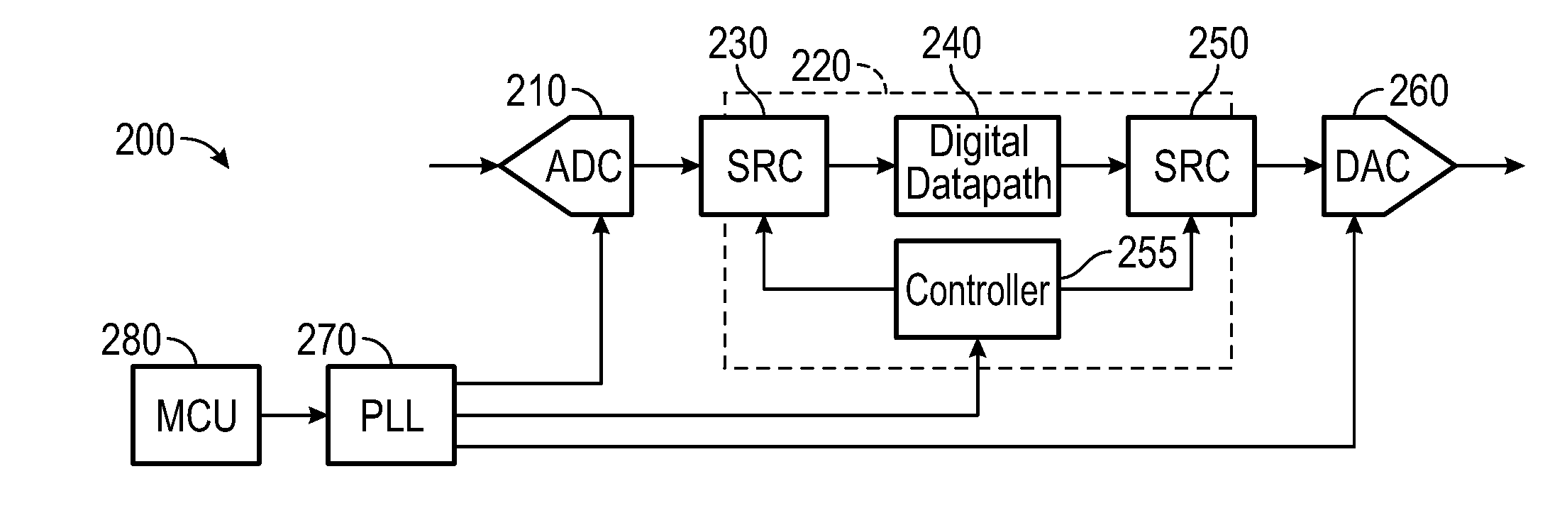
[0026]In various embodiments a frequency management system employs a pair of arbitrary rate sample rate converters (SRCs) to alleviate distortion caused by switching sampling rates in a mixed signal device such as a RF receiver (e.g., a TV receiver). The first SRC is placed at the start of a digital datapath and is configured to convert samples received at a variable rate from a digitizer such as an analog-to-digital converter (ADC) to a fixed, virtual rate. Note that this fixed rate is an average fixed rate that is obtained from selecting cycles at the variable rate, while certain other cycles at the variable rate are inactive or dropped. Subsequent digital processing is done at the virtual rate or at fixed multiples or divisions of the virtual rate. Following the digital datapath, just before a digital-to-analog converter (DAC), the second SRC is used to convert samples from the virtual rate, or a fixed multiple or division of the virtual rate, to the variable DAC sample rate. A c...


PUM


Abstract

In one embodiment, an apparatus includes a first receiver path with a first digitizer to digitize an incoming signal obtained from a radio frequency signal including at least a first desired channel into samples, the first digitizer to operate at a first sampling frequency, a first sample rate converter coupled to an output of the first digitizer to receive the samples at the first sampling frequency and to output the samples at a fixed sampling frequency, and a first digital processor to receive and process the samples at the fixed sampling frequency. The apparatus may further include a controller to receive a frequency change indication and to dynamically control the first sample rate converter to accommodate a change in the first sampling frequency from a first rate to a second rate.

Description

BACKGROUND[0001]In a mixed signal environment, switching noise from clocked and discrete-time elements creates noise that couples into sensitive analog nodes, such as of a radio frequency (RF) receiver. Due to the rapid switching, harmonics of the switching frequencies generate frequency domain spurs that can extend across an entire receiver band of interest.[0002]Traditionally, these spur frequencies have been managed by adjusting the clock frequencies so that harmonics of the switching frequencies do not fall on top of the desired signal. For terrestrial TV tuners, the clock frequency can be adapted by up to + / −4%. A drawback of this approach is that digital signal processing (DSP) elements such as filters and mixers need to be adjusted due to the change in sampling rate. This raises costs in area and power, and makes dynamic switching of the frequency difficult.[0003]Dynamic switching refers to changing of a clock frequency at which the receiver operates on-the-fly, while a TV ch...

Claims


Application Information

Patent Timeline
Patent Type & Authority Applications(United States)
IPC IPC(8): H03H17/06H03M1/12H03M1/06
CPCH03H17/0628H03M1/125H03M1/0614H03H17/028
Inventor TRAGER, DAVIDLIU, ZHONGCHUN
Owner SILICON LAB INC
Why Eureka
Try Eureka