Optical biological measurement device and analysis method using the same

a biological measurement and optical technology, applied in the field of optical biological measuring devices using light and analysis methods, can solve the problem of not being able to achieve precise diagnosis whether cerebral ischemia has taken place or not, and achieve the effect of accurate diagnosis

Active Publication Date: 2015-07-23
SHIMADZU CORP
View PDF0 Cites 5 Cited by
  • Summary
  • Abstract
  • Description
  • Claims
  • Application Information

AI Technical Summary

Benefits of technology

[0039]As described above, in the optical biological measuring device of the present invention, since the removal target second independent component signal S1(t) is found from among numerical N second independent component signals Sn(t) by using the first observation signals H(t) almost all of which includes the signal based on the blood flow in the skin, it is possible to accurately diagnose whether or not symptoms such as cerebral ischemia are generated also in the case of regionally measuring the brain.
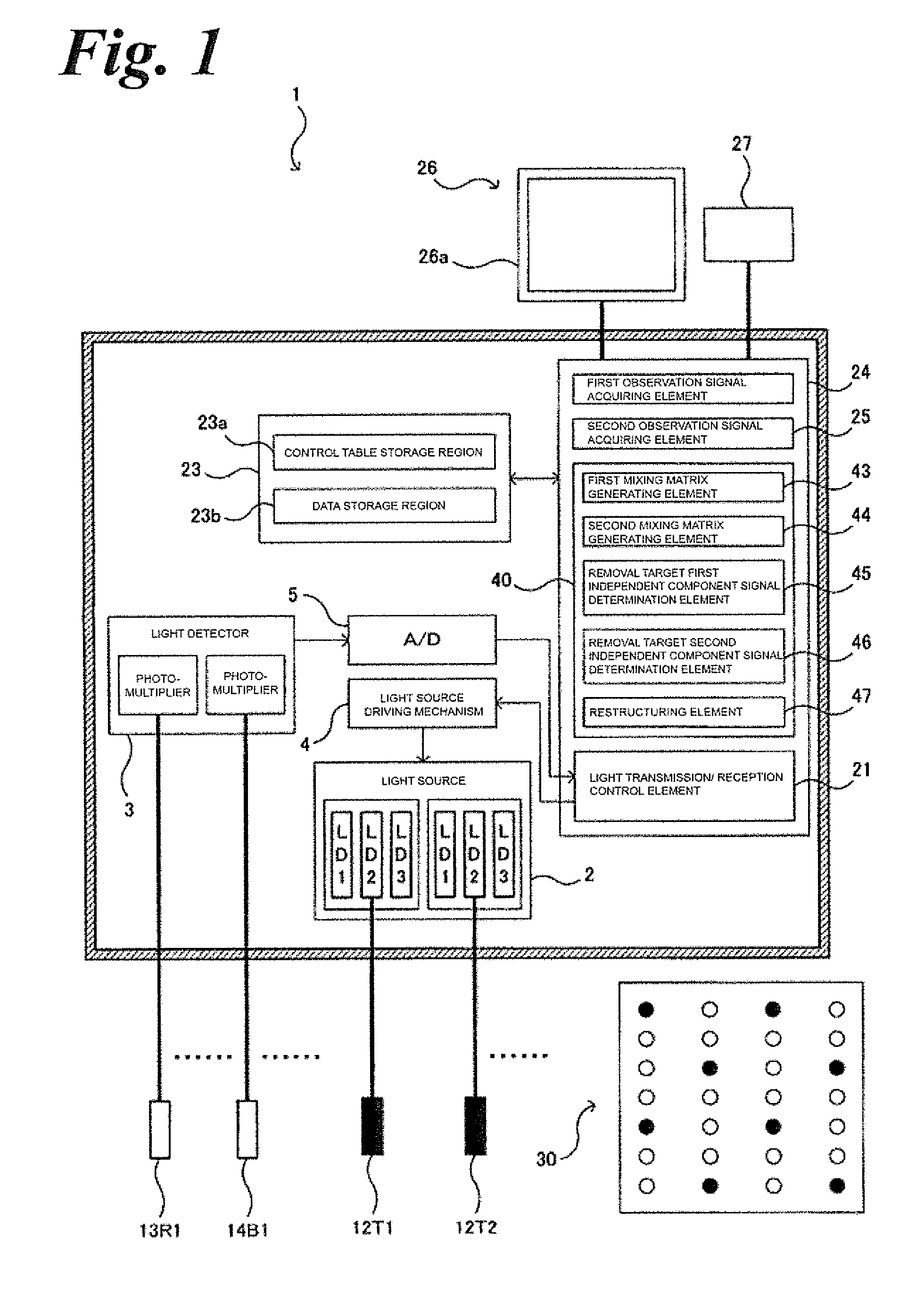
[0040]Further, in the optical biological measuring device of the present invention, a plurality of reference probes is arranged in the light transmission / reception element, and the analysis control element includes a first mixing matrix generating element for separating a plurality of first observation signals into products of a first mixing matrix and a plurality of first independent component signals through independent component analysis, and a removal target first independent component signal determination element for finding a removal target first independent component signal from among the plurality of first independent component signals. The removal target second independent component signal determination element calculates correlation coefficients between the removal target first independent component signals and the second independent component signals, and may determine a signal where the correlation coefficient is a threshold or more as the removal target second independent component signal.
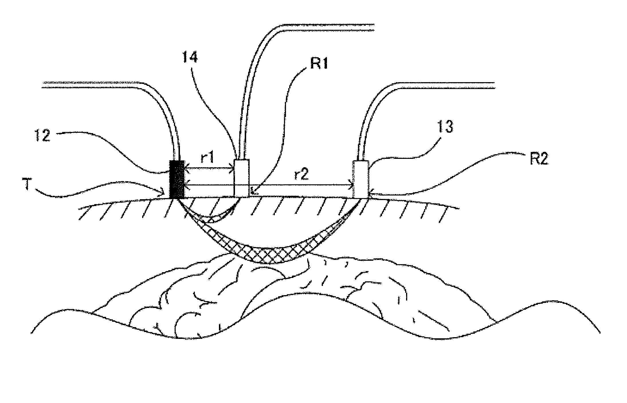
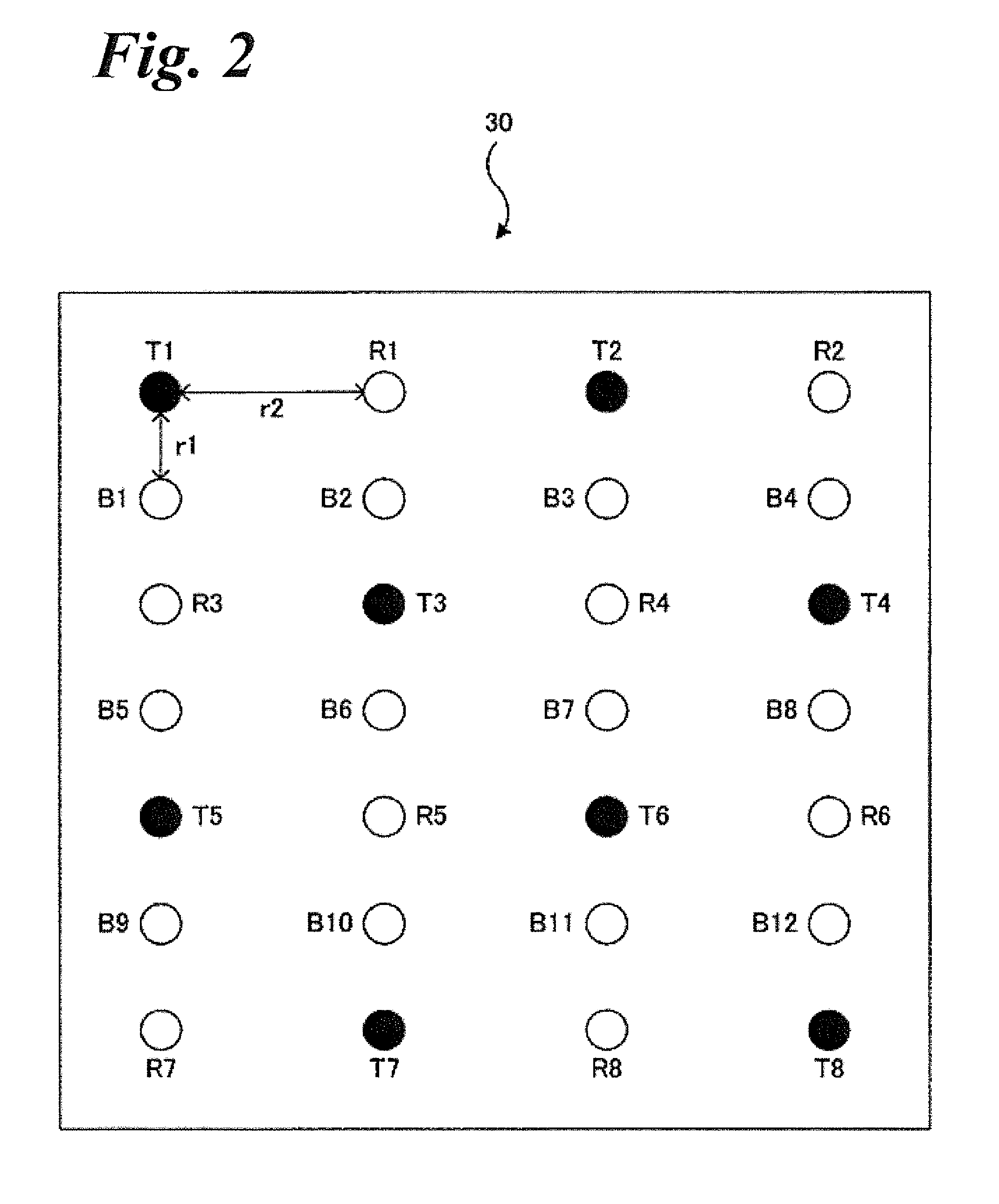
[0041]In the optical biological measuring device of the present invention, the first observation signal acquiring element allows the light transmission probe to irradiate the scalp surface with light and control the reference probe in order to detect light emitted from the scalp surface, and thus numerical M first observation signals Hm(t) concerning numerical M measurement sites are acquired. The first observation signals Hm(t) mostly include the signal based on the blood flow in the skin, but few of them include the signal based on the blood flow according to the brain activity.
[0042]Therefore, the analysis control element finds the signal corresponding to the removal target component from among the first observation signals Hm(t). Also at this time, the independent component analysis is used. First, the first mixing matrix generating element, as shown by the following formula (7), separates numerical M first observation signals Hm(t) into products of an M×M first mixing matrix and numerical M first independent component signals Um(t) through independent component analysis. Herein, when there is a signal generating source of the signal based on the blood flow in the skin, which is irrelevant of the signal based on the blood flow according to the brain activity, it is considered that any of numerical M second independent component signals Um(t) is the signal based on the blood flow in the skin from the signal generating source. The number of signals to be determined as the signals corresponding to the removal target component is not limited to one, and may be two or more.[MathematicalFormula3](H1(T)H2(T)⋮Hm(T))Firstobservationsignal=(b11b12…b1mb21b22…b2m⋮⋱⋮bm1bm2bmm)Firstmixingmatrix(U1(T)U2(T)⋮Um(T))Firstindependentcomponentsignal(7)
[0043]Next, the removal target first independent component signal determination element finds a removal target first independent component signal from among numerical M first independent component signals Um(t). For example, as shown by the following formula (8), the maximum mixing coefficient bmax is found from among each line vector in the M×M first mixing matrix so as to be circled, and the removal target first independent component signal is found based on the number of the maximum mixing coefficients bmax present in each column vector (for example, 2 or more), and threshold mixing coefficients bover that are a threshold bth or more is found from among each line vector in the M×M first mixing matrix. The removal target first independent component signal is found based on the number of the threshold mixing coefficients bover present in each column vector (for example, 2 or more).
[0044]The formula (8) shows a case where the number of the maximum mixing coefficients bmax present in the second column vector is two or more and a first independent component signal U2(t) is the removal target first independent component signal.

Problems solved by technology

The optical biological measuring device using above independent component analysis, however, utilizes signals based on the blood flow in the skin, which are not localized, it is effective only on the wide range measurement of the brain but no precise diagnosis whether a cerebral ischemia have taken place or not might be achieved when the local cerebral area was measured.

Method used


Image

  • Optical biological measurement device and analysis method using the same
  • Optical biological measurement device and analysis method using the same
  • Optical biological measurement device and analysis method using the same

Examples


Embodiment Construction

[0062]Reference will now be made in detail to embodiments of the invention. Wherever possible, same or similar reference numerals are used in the drawings and the description to refer to the same or like parts or steps. The drawings are in simplified form and are not to precise scale. The words ‘couple’ connected ‘linked’ and similar terms do not necessarily denote direct and immediate connections, but also include connections through intermediate elements or devices. For purposes of convenience and clarity only, directional (up / down, etc.) or motional (forward / back, etc.) terms may be used with respect to the drawings. It will be further understood that certain terms, such as ‘data’ may be plural or singular a suited to the circumstance, and that there shall be no limitation on such use, so that ‘a data’ or ‘the data’ or simply ‘data’ may be plural or singular. It will also be understood that the phrases ‘time-course’ or ‘chronological’ will be understood as relative terms of the p...


PUM


Abstract

An optical biological measuring device includes a light transmission / reception element 30 having a plurality of light transmission probes 12, light reception probes 13 and reference probes 14; a second observation signal acquiring element 25 for acquiring a second observation signal indicating a time-course variation relating to a cerebral activity; a first observation signal acquiring element 24 for acquiring a first observation signal indicating a time-course variation relating to the blood flow in the skin; and an analysis control element 40 for generating a removal target component removal observation signal based on the first and second observation signals.

Description

CROSS REFERENCE TO RELATED APPLICATIONS[0001]This application claims priority from and relates to International App. Ser. No. PCT / JP2012 / 069209 filed Jul. 27, 2012, the entire contents of which are incorporated herein by reference.FIGURE SELECTED FOR PUBLICATION[0002]FIG. 7BACKGROUND OF THE INVENTION[0003]1. Field of the Invention[0004]The present invention relates to an optical biological measuring device using light and analysis method for acquiring an observation signal indicating time-course (chronological) variations in terms of a measurement site. Particularly, the present invention is used as an optical cerebral function imaging apparatus for measuring an activity situation of a cerebral measurement site in a noninvasive manner using near-infrared rays, and an oxygen monitor for monitoring oxygen consumption in a measurement site in a living body.[0005]2. Description of the Related Art[0006]In recent years, in order to observe a cerebral activity situation, optical cerebral f...

Claims


Application Information

Patent Timeline
Patent Type & Authority Applications(United States)
IPC IPC(8): A61B5/00
CPCA61B5/0082A61B5/7203A61B5/6814A61B5/4064A61B5/14553A61B5/0261A61B5/14551
Inventor ISHIKAWA, AKIHIROINOUE, YOSHIHIRO
Owner SHIMADZU CORP
Why Eureka
Try Eureka