Continuous real-time CSF flow monitor and method

a continuous real-time, csf technology, applied in medical science, intracranial pressure measurement, diagnostics, etc., can solve problems such as brain damage and death, shunt failure, and generate $2 billion in annual us healthcare costs

Inactive Publication Date: 2015-07-23
SHUNTCHECK
View PDF5 Cites 5 Cited by
  • Summary
  • Abstract
  • Description
  • Claims
  • Application Information

AI Technical Summary

Benefits of technology

[0020]FIG. 2B depicts a Micro-Pumper device that vibrates the shunt valve, generating a temporary increase in shunt flow in patent, but not in occluded shunts, thereby enabling the ShuntCheck to differentiate intermittently flowing patent shunts from obstructed shunts;

Problems solved by technology

Hydrocephalus is a condition in which CSF accumulates in the brain ventricles, potentially leading to brain damage and death.
Hydrocephalus affects 300,000 Americans and generates $2 billion in annual US healthcare costs.
However, shunts fail, typically by obstruction.
Additionally, regular, ongoing clinical management of shunted hydrocephalus patients is also complex.
CSF over drainage can result in symptoms.
In addition, clinical information about the performance of specific shunt valves and siphon control devices is limited.
Current methods for detecting shunt malfunction and for optimizing shunt function do not meet the needs of hydrocephalus patients.
Physical examination, including pumping of the shunt reservoir, is unreliable.
Computed tomography (CT) scans remain the gold standard, but are expensive and cannot be used to investigate every headache, and results in repeated radiological exposures of patients (often children).
Radionuclide shunt flow testing is invasive and poses a risk of infection.
New technologies under development are complex (advanced magnetic imaging resonance (MRI) techniques, ultrasound tracking of bubbles), lacking in precision (forward looking infrared, FLIR) or require implantation (implanted thermal flow technologies) and have not reached the clinic.
However, the short duration of the test limits its utility for shunt valve adjustment, investigating suspected shunt over-drainage, etc.

Method used


Image

  • Continuous real-time CSF flow monitor and method
  • Continuous real-time CSF flow monitor and method
  • Continuous real-time CSF flow monitor and method

Examples


Embodiment Construction

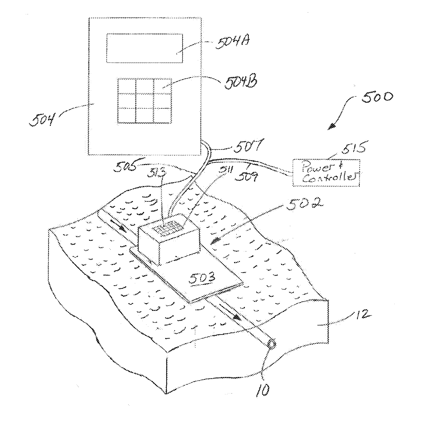
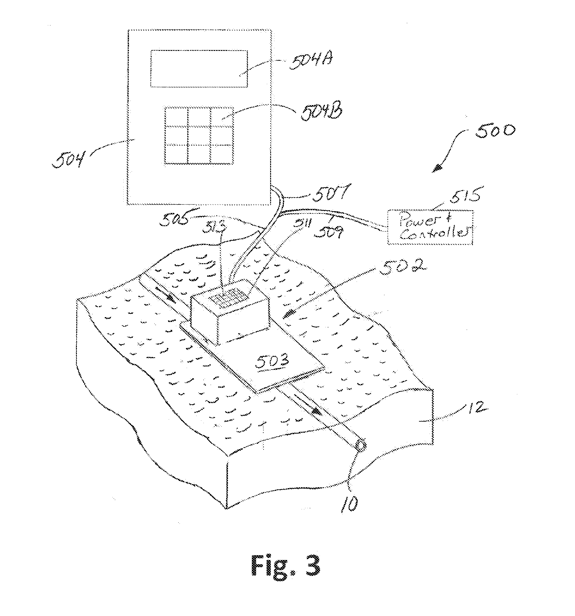
[0039]The present invention 500 is termed a “continuous real-time (CRT)” CSF flow monitor and method. This device provides improved care for hydrocephalus patients by providing a rapid and non-invasive method for monitoring changes in CSF flow in shunted patients. As a result, the present invention 500 directly responds to such demands for diagnostic tools for use in a hospital or outpatient settings that work in real-time to quantitatively determine shunt function.

[0040]As is discussed in detail later, a key aspect the present invention 500 uses non-invasive thermal dilution technology to monitor changes is CSF flow over extended periods of time, enabling neurosurgeons to assess in real-time the impact of changes—of valve setting, patient position, etc.,—on shunt flow. This cannot be accomplished in any way with current technologies and represents an important new tool for managing hydrocephalus. As will also be discussed later, a “Peltier sensor” of the present invention 500 repre...


PUM


Abstract

An apparatus and method for determining a continuous CSF flow rate in an implanted CSF shunt in real-time. The system/method utilize a Peltier sensor formed on a flexible pad that is placed against the patient's skin. The Peltier sensor includes a Peltier device coupled to a thermal resistor that is contact with the patient's skin over the CSF shunt location. The Peltier device is operated continuously, controlled by the Peltier temperature sensor to a predetermined temperature that is below the patient's core temperature to form a temperature differential that causes any heat generated by the skin/CSF flow to be detected by a skin temperature sensor and the Peltier temperature sensor. Upstream and downstream temperature sensors, as well as control temperature sensors, are utilized to form a zero flow rate baseline that is used to calibrate a Peltier signal that corresponds to a real-time CSF flow rate. A sensor processing device processes all sensor data for generating the zero flow rate baseline and the Peltier signal.

Description

CROSS-REFERENCE TO RELATED APPLICATIONS[0001]This PCT application claims the benefit under 35 U.S.C. §119(e) of Provisional Application Ser. No. 61 / 742,048 filed on Aug. 2, 2012 entitled CSF FLOW MONITOR and whose entire disclosure is incorporated by reference herein.BACKGROUND OF THE INVENTION[0002]1. Field of Invention[0003]This present invention generally relates to cerebrospinal fluid (CSF) shunts and, more particular, to a device and method for a continuous, real-time (CRT) monitor of CSF flow through shunt tubing implanted under the skin in hydrocephalus patients.[0004]2. Description of Related Art[0005]Hydrocephalus is a condition in which CSF accumulates in the brain ventricles, potentially leading to brain damage and death. Approximately 69,000 people are diagnosed with hydrocephalus each year in the United States. Hydrocephalus affects 300,000 Americans and generates $2 billion in annual US healthcare costs.[0006]Hydrocephalus is corrected by placing a ventricular-peritone...

Claims


Application Information

Patent Timeline
Patent Type & Authority Applications(United States)
IPC IPC(8): A61B5/00A61M27/00A61B5/01
CPCA61B5/4851A61B5/01A61B5/4058A61M27/006A61B5/4836A61B2560/0223A61B2562/0271A61B2562/043A61B2560/0412A61B2562/164A61B5/7278A61B5/031
Inventor SWOBODA, MAREKHOCHMAN, MATIAS GABRIEL
Owner SHUNTCHECK
Why Eureka
Try Eureka