Non-Rotatable Telescopic Handle Construction

a telescopic handle and non-rotatable technology, applied in the field of telescopic handles, can solve the problems of extending the telescopic handle with unnecessary force, exacerbated problems, and difficult implementation of cam locking structures, and achieve the effect of reducing the amount of flex in the handle and adding strength to the handl

Active Publication Date: 2015-07-23
BAG BOY
View PDF5 Cites 19 Cited by
  • Summary
  • Abstract
  • Description
  • Claims
  • Application Information

AI Technical Summary

Benefits of technology

[0011]In another form, each of the handle sections is formed with an axially extending groove at at least one circumferential location although, in a preferred form, two axial grooves are formed at 180 degree displacement around the handle section. The grooves are arranged and sized so that the handle sections slide together with a groove in one section fitting into a groove in each overlapping section. This interlocking of the grooves prevents the sections from independently twisting thereby maintaining the position of the head of the ball retriever. In addition, the grooves add strength to the handle thereby reducing the amount of flex in the handle when extended.

Problems solved by technology

Cam locking structures are difficult to implement in the smaller retrievers due to this reduced diameter.
One problem with this small handle construction is that a golfer who has to use the retriever is often angry and will attempt to extend the telescopic handle with unnecessary force.
As a result, the small dimple can shear away and allow the sections to separate and destroy the retriever.
This problem is exacerbated in better quality retrievers made from thin wall, stainless steel tubing since the thin wall has a near knife edge and easily shears the bronze shim material.
Unfortunately, there are occasions in which the user of the handle will jerk the extensions so hard that the shim is distorted and the smaller diameter tube will slip over the shim and cause the tubes to separate.
As explained in the '228 patent, when the handle is extended, the weight of the several extending tubes causes the handle to deflect to a relatively large extent making the handle difficult to accurately position and put pressure on an object at the distal end of the handle.
For example, in the case of a golf bail retriever using a form of cup at the end of the handle for grasping a golf ball, the friction fit between each of the tube sections may allow the tubes to rotate with respect to each other such that any resistance at the retriever cup may allow it to rotate and inhibit the ability to retrieve the golf ball.
However, with the shorter retrievers that only rely on friction fit, rotation becomes an issue.

Method used


Image

  • Non-Rotatable Telescopic Handle Construction
  • Non-Rotatable Telescopic Handle Construction
  • Non-Rotatable Telescopic Handle Construction

Examples


Embodiment Construction

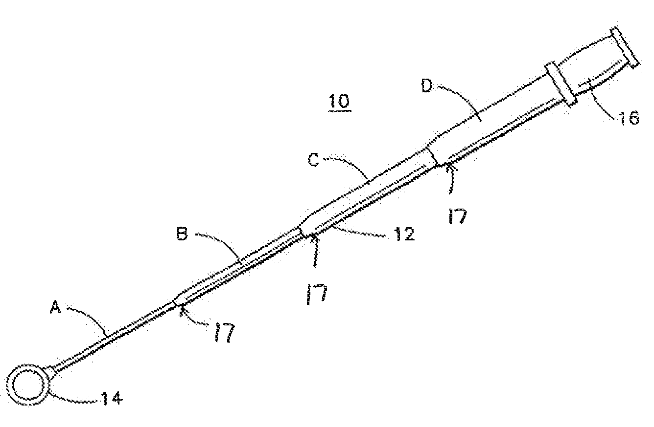
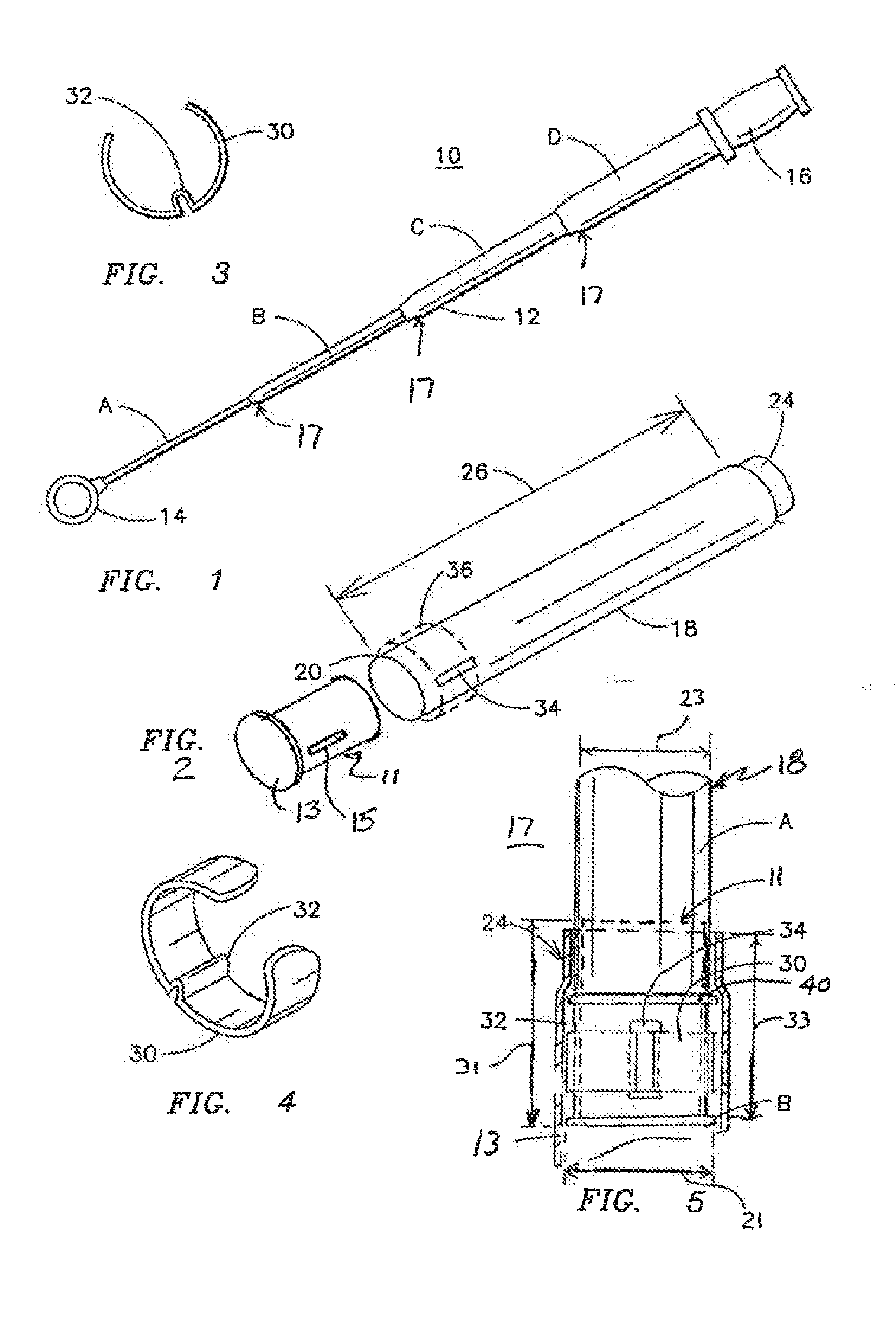
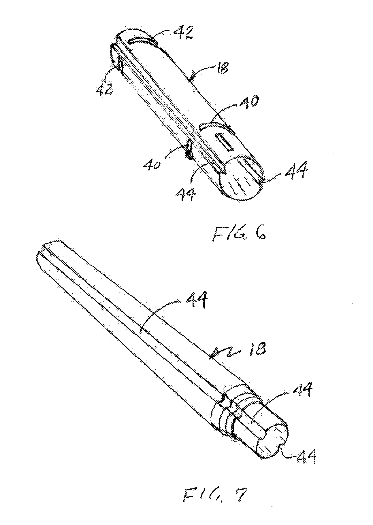
[0020]Applicant has found that telescoping handles, when positioned in an extended state, could be made stiffer and avoid many of the bending problems associated with prior telescoping handles using a small stiffener, or plug, at the juncture of each joint of the retriever. The details of such a handle is shown and described in U.S. Pat. No. 7,073,228, the disclosure of which is hereby incorporated by reference. The present invention is an improvement over the invention of the '228 patent to further enhance stiffness of the extended telescoping handle and to reduce the chance of separation of the individuals segments of the handle.

[0021]Turning now to the drawings in general and in particular to FIGS. 1, 3 and 4, the invention will now be described in the context of a golf ball retriever having a handle 12 and grip 16 and comprising a plurality of telescoping segments or tubes 18, each of which has a sequentially smaller diameter and sequentially shorter length, and a ball grabbing ...


PUM


Abstract

A golf ball retriever handle having a plurality of telescoping segments, each segment comprising a tubular member configured to fit relatively snugly about an adjacent member in sliding engagement therewith, each of the members between the smallest diameter member and the largest diameter member being formed with a radially extending annular rib in proximity to a first end thereof and being formed with a radially inward extending annular depression in proximity to a second end thereof, whereby separation of the tubular members in a handle extending direction is inhibited. The handle also having at least one axial groove formed in each section such that overlapping grooves engage each other to prevent rotation of one section with respect to another.

Description

FIELD OF THE INVENTION[0001]The present invention relates to telescoping handles for various implements such as, for example, golf ball retrievers.BACKGROUND OF THE INVENTION[0002]Golf ball retrievers are well known devices generally constructed of a telescoping handle with a ball trapping or pick-up element attached to an end of the ultimate section of the handle. An exemplary form of such a retriever is shown in U.S. Pat. No. 5,265,926 of Frank L. DiNardo. The telescopic handle of such retrievers is formed of a plurality of sections and may be extendable from a collapsed length of about 3 feet to an extended length of about 18 feet. However, there are also other retrievers which may have a collapsed length of about 1 foot and extend to about 8 feet. Obviously, a 1 foot retriever extending to 8 feet requires at least eight telescoping sections.[0003]The larger retrievers, i.e., those having an initial length of about 3 feet, generally use large diameter tubing, e.g., about 1 inch O...

Claims


Application Information

Patent Timeline
Patent Type & Authority Applications(United States)
IPC IPC(8): B25G1/04A63B47/02
CPCA63B47/02B25G1/04A63B2225/093A63B2102/32
Inventor LIGHT, ALBERT JAMES
Owner BAG BOY
Why Eureka
Try Eureka