Heat pipe

Active Publication Date: 2015-07-23
THE FUJIKURA CABLE WORKS LTD
View PDF0 Cites 20 Cited by
  • Summary
  • Abstract
  • Description
  • Claims
  • Application Information

AI Technical Summary

Benefits of technology

[0021]According the present invention, the inner surface of the container may be covered entirely with the porous wick holding the fiber wick. In this case, the working fluid can be spread homogeneously all over the wick structure. In addition, a thermal resistance between the inner face of the container and an outer face of the porous wick can be reduced.
[0022]In case of using the flat container, only the inner flat face of the flat portion contacted to the heat-generating object is covered with the porous wick holding the fiber wick. In this case, an air passage can be ensured sufficiently in the container so that the working fluid is allowed to be returned efficiently to the evaporating portion. Consequently, the heat

Problems solved by technology

However, according to the heat pipe taught by US2012/0118537 A, a pressure loss of the wick struct

Method used


Image

  • Heat pipe
  • Heat pipe
  • Heat pipe

Examples


Embodiment Construction

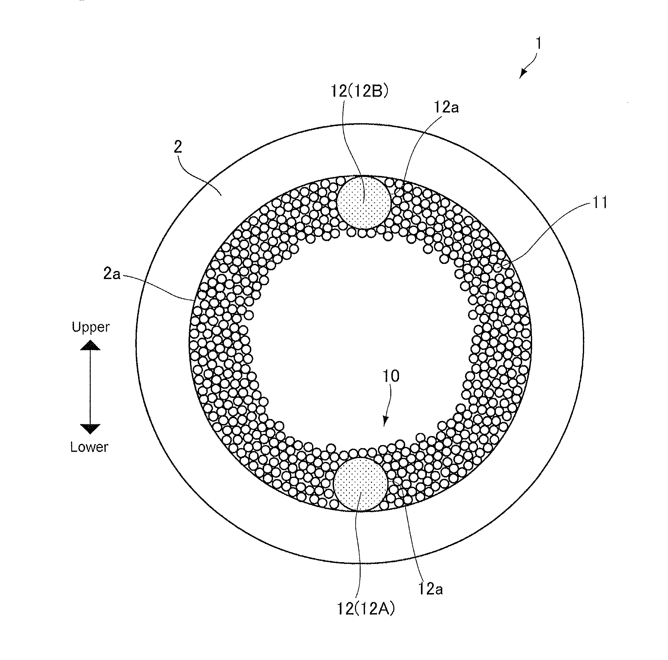
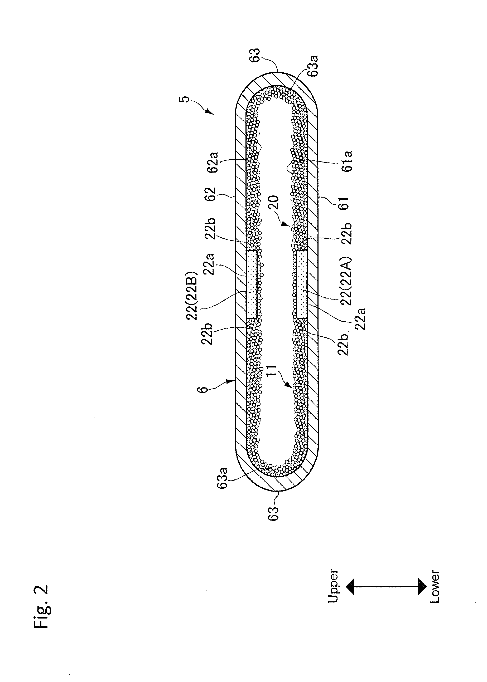
[0030]Preferred examples of the present invention will now be explained in more detail with reference to the accompanying drawings. The heat pipe of the present invention is comprised of working fluid encapsulated in a sealed container, a porous wick structure constructed of a sintered metal powder, and a water channel arranged in the porous wick. The water channel is constructed of bundled metal fibers so that fluid flow resistance of the water channel is smaller than that of the porous wick. The working fluid is evaporated when it is heated, and condensed when heat is removed therefrom.

[0031]Referring now to FIG. 1, there is shown cross-section of the heat pipe according to the first example of the present invention. In FIG. 1, the arrow situated beside the heat pipe 1 indicates the vertical direction of the heat pipe 1.

[0032]The first example relates to a cylindrical heat pipe having a container 2 whose cross-sectional shape is round. The container 2 is a cylindrical member made ...


PUM


Abstract

A heat pipe having a wick structure for efficiently returning working fluid to an evaporating portion is provided. The heat pipe comprises a container 2 sealed at its both ends, a working fluid encapsulated in the container, and a wick structure 10 covering an inner face of the container. The wick structure 10 includes a porous wick 11 of a sintered metal powder, and a fiber wick 12 buried in the porous wick. A capillary pressure of the fiber wick 12 is weaker than that of the porous wick 11, and a pressure loss of the fiber wick 12 is smaller than that of the porous wick 11.

Description

[0001]The present invention claims the benefit of Japanese Patent Applications No. 2014-007012 filed on Jan. 17, 2014 with the Japanese Patent Office, the disclosures of which are incorporated herein by reference in its entirety.BACKGROUND[0002]1. Field of the Invention[0003]The present invention relates to the art of a heat pipe having a wick structure constructed of sintered metal powder arranged in a sealed container.[0004]2. Discussion of the Related Art[0005]Conventional heat pipes are adapted to absorb heat from a heat generating object such as an electronic device in the form of latent heat of working fluid. In the heat pipe, the working fluid is evaporated by an external heat and condensed while radiating heat. Cooling performance of the heat pipe of this kind may be enhanced by increasing mass flow of the working fluid.[0006]In recent years, electronic devices has been downsized and highly improved hence generate higher heat. Therefore, the heat pipes are required to be dow...

Claims


Application Information

Patent Timeline
IPC IPC(8): F28D15/02
CPCF28D15/02F28D15/0233F28D15/046
Inventor THANHLONG, PHANSAITO, YUJIMOCHIZUKI, MASATAKA
Owner THE FUJIKURA CABLE WORKS LTD
Why Eureka
Try Eureka