
3D scanner using structured lighting

a structured lighting and scanner technology, applied in the field of methods and systems for determining 3d information using structured lighting, can solve problems such as insufficient robustness of techniques

Active Publication Date: 2015-07-23
KONINKLJIJKE PHILIPS NV
View PDF16 Cites 15 Cited by
  • Summary
  • Abstract
  • Description
  • Claims
  • Application Information

AI Technical Summary

Benefits of technology

The patent describes a method for identifying intensity features in an image using structured lighting patterns. The method minimizes the risk of miss-identification by identifying the positions of intensity features in a first subset of the image and then identifying the positions of intensity features in a second subset based on the positions of the first subset. The method also compensates for motion in the image by analyzing the positions of intensity features in consecutive images and using them to identify the positions of intensity features in the second subset. The method can be used with a plurality of preceding structured lighting patterns to increase its robustness against invisibility of features in some images.

Problems solved by technology

However, these techniques are still not completely robust.

Method used


Image

  • 3D scanner using structured lighting
  • 3D scanner using structured lighting
  • 3D scanner using structured lighting

Examples


Embodiment Construction

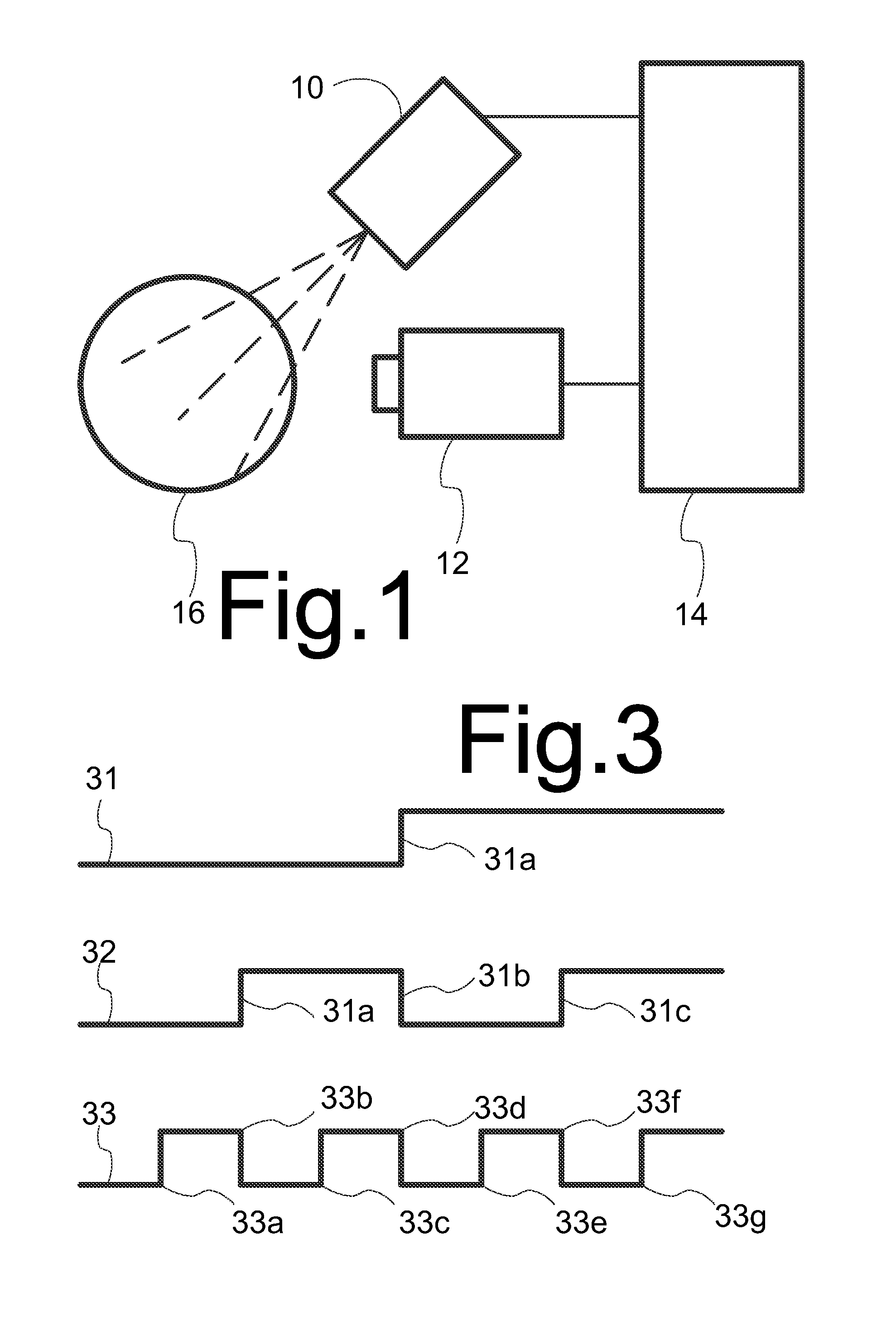
[0021]FIG. 1 shows a system for determining 3D surface position information, comprising a light source 10, a camera 12, and a processing system 14 coupled to light source 10 and camera 12. Light source 10 and camera 12 are both directed at an object 16 from different positions.

[0022]In operation, light source 10 projects a series of lighting patterns P(n) (n=0, 1, . . . ) onto object 16 and camera 12 captures images IM(n) of object 16 when object 16 is illuminated by the respective patterns. In the following, lighting patterns P(n) will be characterized by intensities in their cross-section with a plane transverse to rays from light source 10 (as used herein, “transverse” is used for not parallel to, for example perpendicular to). The three dimensional structure of the lighting pattern follows from this cross-section and the properties of light source 10. For example, in the case of a divergent light source, the lighting pattern comprises a collection of light rays in a continuum of...


PUM


Abstract

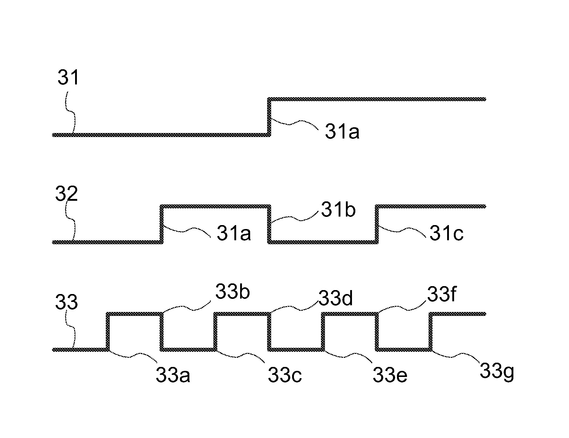
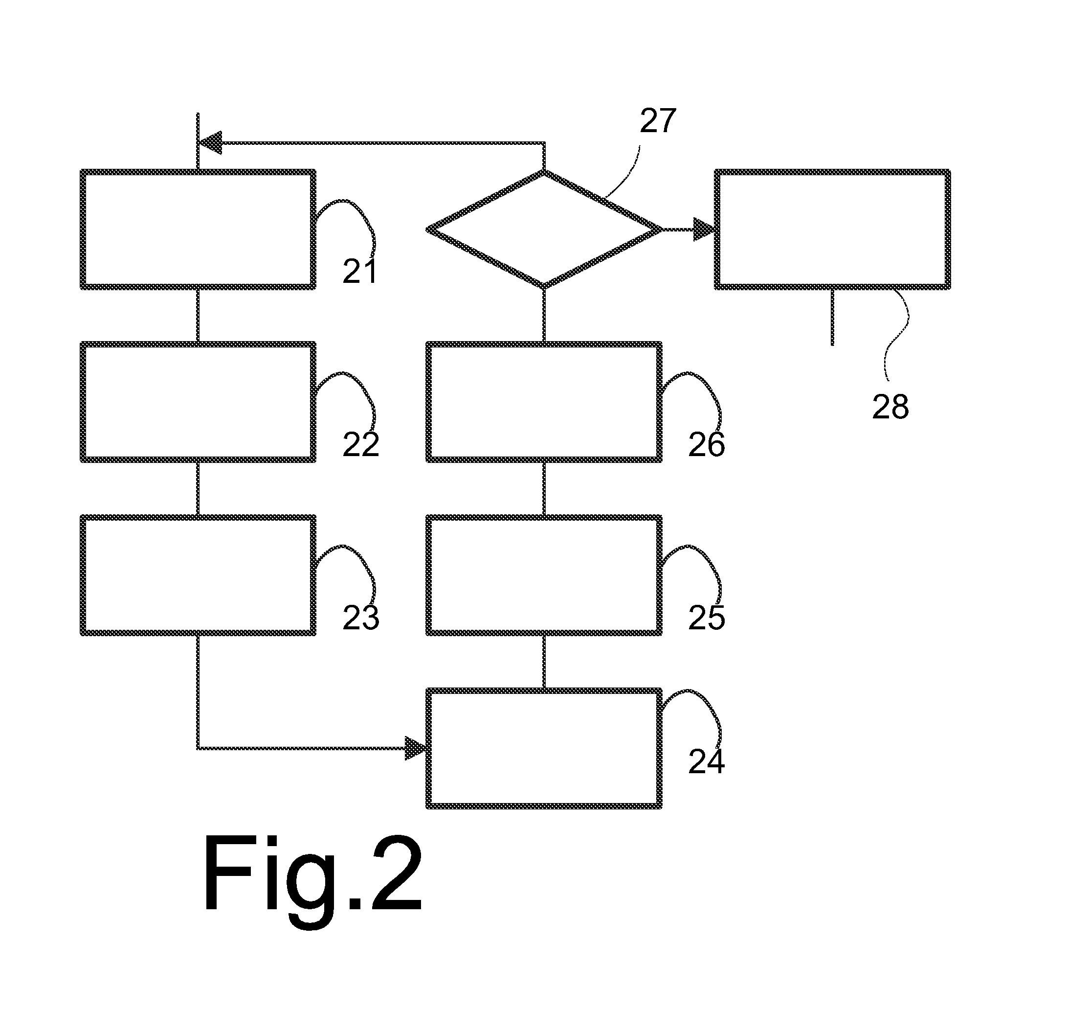
A series of structured lighting patterns are projected on an object. Each successive structured lighting pattern has a first and second subset of intensity features such as edges between light and dark areas. The intensity features of the first set coincide spatially with intensity features from either the first or second subset from a preceding structured lighting pattern in the series. Image positions are detected where the intensity features of the first and second subset of the structured lighting patterns are visible in the images. Image positions where the intensity features of the first subset are visible are associated with the intensity features of the first subset, based on the associated intensity features of closest detected image positions with associated intensity features in the image obtained with a preceding structured lighting pattern in said series. Image positions where the intensity features of the second subset are visible, between pairs of the image positions associated with intensity features of the first subset, with intensity features of the second subset between the intensity features associated with the pair of positions. The associated intensity features in a final structured lighting pattern of the series are used to identify the intensity features of the final structured lighting pattern for the determination of 3D surface position information.

Description

FIELD OF THE INVENTION[0001]The invention relates to a method and system for determining 3D information using structured lighting.BACKGROUND OF THE INVENTION[0002]Structured lighting is a well known technique for use in extraction of 3D information from a scene. The extraction of 3D information is based on the projection of a known lighting pattern on a scene, and capturing of the resulting image with a camera of the scene. The technique works on the basis of disparity (as when a stereo-camera is used), with a distance (often called the baseline) between the camera and a projector that projects the lighting pattern. As a result of this disparity, one can determine the depth of an object (seen from the camera). Similar to a stereo-camera, such a system can estimate depth, but as we project lighting structures (patterns), the system also works on uniform objects, which is not the case for a stereo camera. Therefore, structured light systems provide much more reliable depth estimation ...

Claims


Application Information

Patent Timeline
IPC IPC(8): G01B11/25G06T7/00
CPCG01B11/2518G06T2207/10028G06T2207/10012G06T7/0057G01B11/2513G01B11/2536G06T7/586G06T2207/10152G06T7/521
Inventor ZNAMENSKIY, DMITRY NIKOLAYEVICHVLUTTERS, RUUDVAN BREE, KARL CATHARINA
Owner KONINKLJIJKE PHILIPS NV
Learn More