
Magnetizing inrush current detection method, magnetizing inrush current restraint method and device

a technology of inrush current and detection method, applied in the direction of voltage-current phase angle, emergency protective circuit arrangement, instruments, etc., can solve the problem of difficult implementation method, and achieve the effect of more accurate recognition of inrush currents

Inactive Publication Date: 2015-07-23
SIEMENS AG
View PDF3 Cites 20 Cited by
  • Summary
  • Abstract
  • Description
  • Claims
  • Application Information

AI Technical Summary

Benefits of technology

The present invention provides an improved method for detecting magnetizing inrush currents in electrical systems. The method takes into account the relationships between the three AC phases, making it more accurate in identifying the current. The method also uses a waveform symmetry algorithm that is faster and more accurate than other algorithms. By calculating waveform symmetry factors from difference currents, the method is less affected by interference from DC components, resulting in higher accuracy. The method also effectively blocks differential protection when a magnetizing inrush current is detected and permits it otherwise, ensuring reliable operation. Additionally, the method allows for rapid cut-off within one cycle when faults of all kinds occur. The presence of a fault phase, such as a grounding of a single phase or an inter-phase fault, does not prevent the method from operating correctly. Overall, the present invention has improved performance in recognizing inrush currents and distinguishing faults.

Problems solved by technology

As a result, there is a strong likelihood that the occurrence of a magnetizing inrush current when the transformer is switched on with no load will erroneously trigger the differential protection action of the transformer, so that the transformer automatically trips in the instant after it is switched on.
When the interruption angle principle is used in microcomputer protection, the high requirements it places on hardware make the implementation method rather difficult.

Method used


Image

  • Magnetizing inrush current detection method, magnetizing inrush current restraint method and device
  • Magnetizing inrush current detection method, magnetizing inrush current restraint method and device
  • Magnetizing inrush current detection method, magnetizing inrush current restraint method and device

Examples


Embodiment Construction

[0022]Various embodiments of the present invention will be described below with reference to the accompanying drawings.

[0023]The following description will facilitate understanding of the above-mentioned advantages of the present invention.

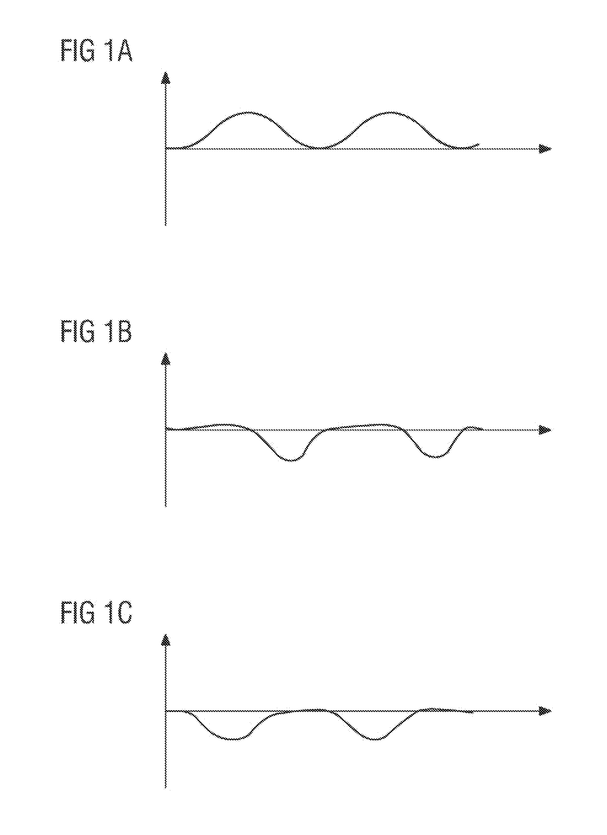
[0024]FIGS. 1A-1C show typical waveforms of magnetizing inrush currents occurring in three AC phases a, b and c of a three-phase transformer by way of example. By studying the characteristics of the magnetizing inrush current waveforms with reference to FIG. 1, it can be determined that the magnetizing inrush currents have the following characteristics.

[0025](1) When a transformer is switched on with no load, whether an inrush current arises and the size of such an inrush current is related to the phase angle at the time of switch-on, the magnetizing inrush current being greatest for phase angles α=0 and α=π at switch-on.

[0026](2) The magnetizing inrush currents in the three phases will be different, because there is a 120° phase difference betwee...


PUM


Abstract

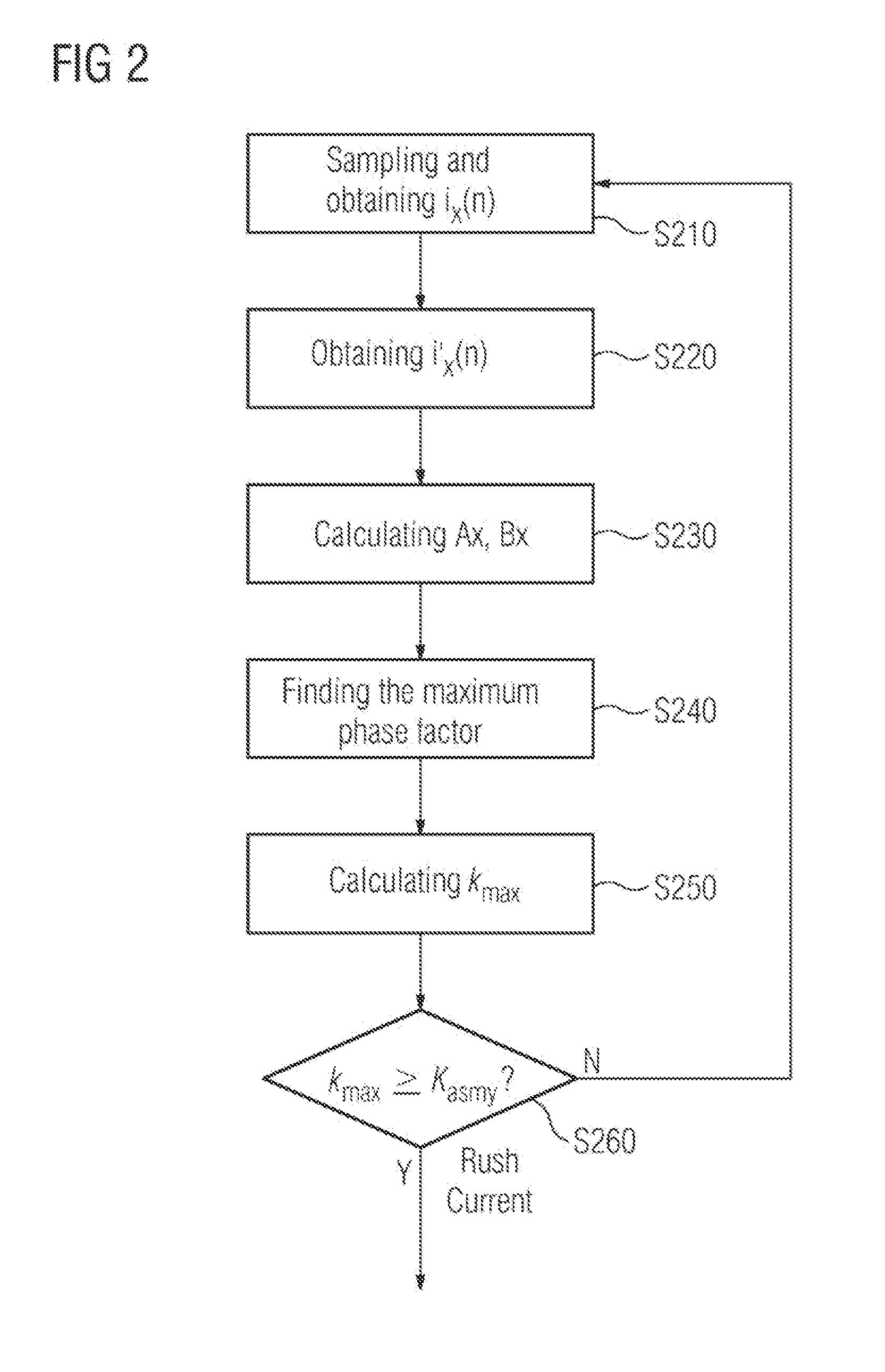
A method for detecting a magnetizing inrush current of a transformer includes the steps of obtaining a difference current for each AC phase of a transformer and calculating, for each AC phase, at least two factors for waveform symmetry recognition, on the basis of the difference currents obtained within one period. For each type of factor, one obtains the maximum value of the three factors corresponding to the three AC phases, to serve as a maximum phase factor of that factor. Based on the maximum phase factor obtained, a waveform symmetry recognition algorithm is used to calculate a corresponding waveform symmetry parameter, and if the waveform symmetry parameter meets a requirement for waveform asymmetry, then it is determined that a magnetizing inrush current has occurred. A device for protecting the transformer is further provided.

Description

TECHNICAL FIELD[0001]The present invention relates to transformer protection technology in general, and in particular to a method and device for detecting the magnetizing inrush current which occurs when a transformer is switched on with no load, and a magnetizing inrush current restraint method and device.BACKGROUND ART[0002]In an electrical system, a large transient current will occur when a transformer is switched on with no load, for instance 6-8 times the rated current of the transformer. This large transient current which occurs when a transformer is switched on with no load is what is known as “magnetizing inrush current” in the art. As a result, there is a strong likelihood that the occurrence of a magnetizing inrush current when the transformer is switched on with no load will erroneously trigger the differential protection action of the transformer, so that the transformer automatically trips in the instant after it is switched on.[0003]The main reason for the occurrence o...

Claims


Application Information

Patent Timeline
IPC IPC(8): G01R19/10G01R25/00H02H7/045
CPCG01R19/10G01R25/00H02H7/045H02H1/043G01R19/0053
Inventor CHEN, SHU DECHEN, WEIGAO, DI JUNLI, JIN HUIQIN, LEI MINGRAO, CHUNYANG, MIN
Owner SIEMENS AG
Learn More