Display device

a display device and display technology, applied in the field of display devices, can solve the problems of reducing the overall display area of the display device and reducing the satisfaction of the consumer with the display device, and achieve the effect of reducing the gap between the parametric capacitance and the overall display area

Active Publication Date: 2015-07-23
SHENZHEN CHINA STAR OPTOELECTRONICS TECH CO LTD
View PDF17 Cites 16 Cited by
  • Summary
  • Abstract
  • Description
  • Claims
  • Application Information

AI Technical Summary

Benefits of technology

[0023]Also, by forming the insulating layer between the common electrode application unit and the transistor circuit unit, the parasitic capacitance therebetween may be reduced.

Problems solved by technology

As the peripheral area surrounding the display area is increased, a bezel of the display device, representing the planar area of the peripheral area is increased, thereby reducing an overall display area of the display device and reducing a consumer's satisfaction for the display device.

Method used


Image

  • Display device
  • Display device
  • Display device

Examples


Embodiment Construction

[0034]Hereinafter, exemplary embodiments of the invention will be described in detail with reference to the accompanying drawings. As those skilled in the art would realize, the described exemplary embodiments may be modified in various different ways, all without departing from the spirit or scope of the invention. On the contrary, exemplary embodiments introduced herein are provided to make disclosed contents thorough and complete, and to sufficiently transfer the spirit of the invention to those skilled in the art.

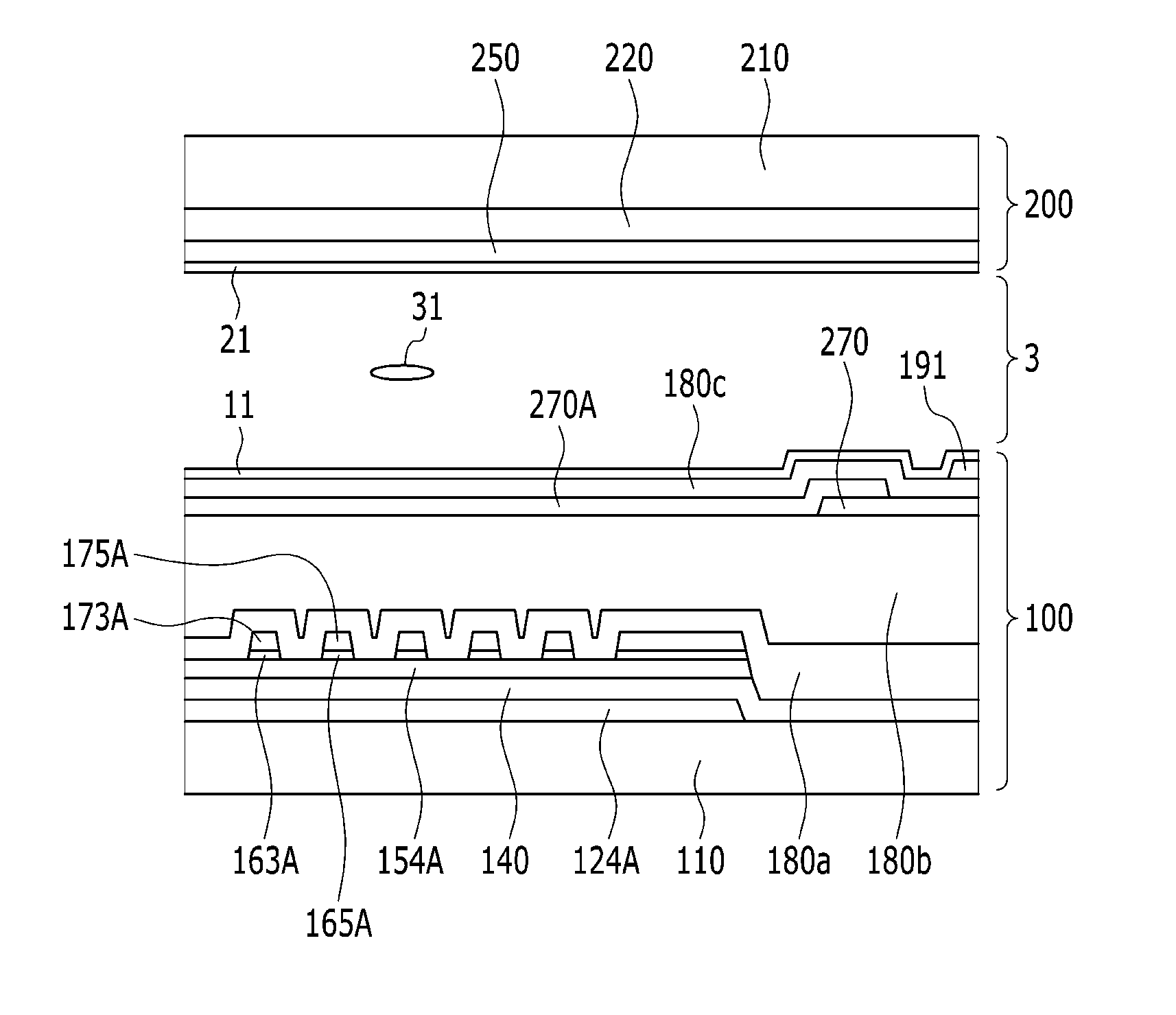
[0035]In the drawings, the thickness of layers, films, panels, regions, etc., are exaggerated for clarity. It will be understood that when a layer is referred to as being “on” another layer or substrate, it can be directly on the other layer or substrate, or intervening elements may also be present. Like reference numerals designate like elements throughout the specification. As used herein, connected may refer to elements being physically and / or electrically connected ...


PUM

PropertyMeasurementUnit
DAaaaaaaaaaa
area DAaaaaaaaaaa
thicknessaaaaaaaaaa

Abstract

A display device is provided. A display device according to an exemplary embodiment of the present invention includes a display panel including: a display area where a plurality of pixels are disposed and a peripheral area near the display area; and a gate driver disposed in the peripheral area and including a transistor unit and a common voltage application unit, wherein the common voltage application unit overlaps via a first insulating layer disposed on the transistor unit.

Description

[0001]This application claims priority to Korean Patent Application No. 10-2014-0006914 filed on Jan. 20, 2014, and all the benefits accruing therefrom under 35 U.S.C. §119, the entire contents of which are incorporated herein by reference.BACKGROUND[0002](a) Field[0003]The invention relates to a display device.[0004](b) Description of the Related Art[0005]In general, a display device includes a plurality of pixels which are an image-displaying unit of the display device and defined in a display panel of the display device, and drivers configured to drive the pixels. The drivers include a data driver applying a data voltage to the pixels, and a gate driver applying a gate signal to the pixels for controlling transfer of the data voltage. The gate driver and / or the data driver are mounted on a printed circuit board (“PCB”) in a chip type structure to be connected to the display panel or the driver chip is mounted directly on the display panel.[0006]For a non-high mobility thin film t...

Claims


Application Information

Patent Timeline
Patent Type & Authority Applications(United States)
IPC IPC(8): G02F1/1345G02F1/1368G02F1/1333G02F1/1362
CPCG02F1/1345G02F1/133345G02F1/1368G02F1/136286G02F1/13454G09G3/3648G09G2300/0408F24D17/0005E03C2001/005Y02T10/12G09G3/36
Inventor KOO, BON-YONGSON, DONG YEON
Owner SHENZHEN CHINA STAR OPTOELECTRONICS TECH CO LTD
Why Eureka
Try Eureka