Surface acoustic wave filter and communication apparatus

a surface acoustic wave and filter technology, applied in piezoelectric/electrostrictive/magnetostrictive devices, piezoelectric/electrostriction/magnetostriction machines, electrical apparatus, etc., can solve the problem of reducing the suppression level of signals, requiring many wiring traces of saw filters with many idts, and increasing the area. problem, to achieve the effect of improving the degree of balance, reducing the parasitic capacitance level between

Inactive Publication Date: 2007-11-13
MURATA MFG CO LTD
View PDF31 Cites 21 Cited by
  • Summary
  • Abstract
  • Description
  • Claims
  • Application Information

AI Technical Summary

Benefits of technology

[0021]To overcome the problems described above, preferred embodiments of the present invention provide a SAW filter in which parasitic capacitance between wiring traces is reduced and the signal suppression level outside the pass band is increased. In addition, preferred embodiments of the present invention provide a SAW filter having an unbalance-to-balance transformer function in which a balanced signal has an improved degree of balance.

Problems solved by technology

Therefore, the parasitic capacitance degrades the suppression level for signals of frequencies outside a pass band.
In particular, a SAW filter having many IDTs requires many wiring traces for connecting the IDTs.
Further, the covered area is increased, parasitic capacitance is more likely to be generated, and the size of the filter is increased.
Therefore, a common-mode signal in each balanced signal increases, such that the degree of balance is deteriorated.
As described above, parasitic capacitance between wiring traces, in particular, parasitic capacitance between wiring traces having different potentials, has a detrimental effect on the characteristic of a SAW filter.
Specifically, when a piezoelectric substrate includes a material having a relative permittivity of more than about 20, for example, LiTaO3, LiNbO3, or Li2B4O7, parasitic capacitance substantially increases, and thus, the detrimental effects are significant.
Therefore, a SAW filter having a higher-frequency pass band is more severely affected.

Method used


Image

  • Surface acoustic wave filter and communication apparatus
  • Surface acoustic wave filter and communication apparatus
  • Surface acoustic wave filter and communication apparatus

Examples


first preferred embodiment

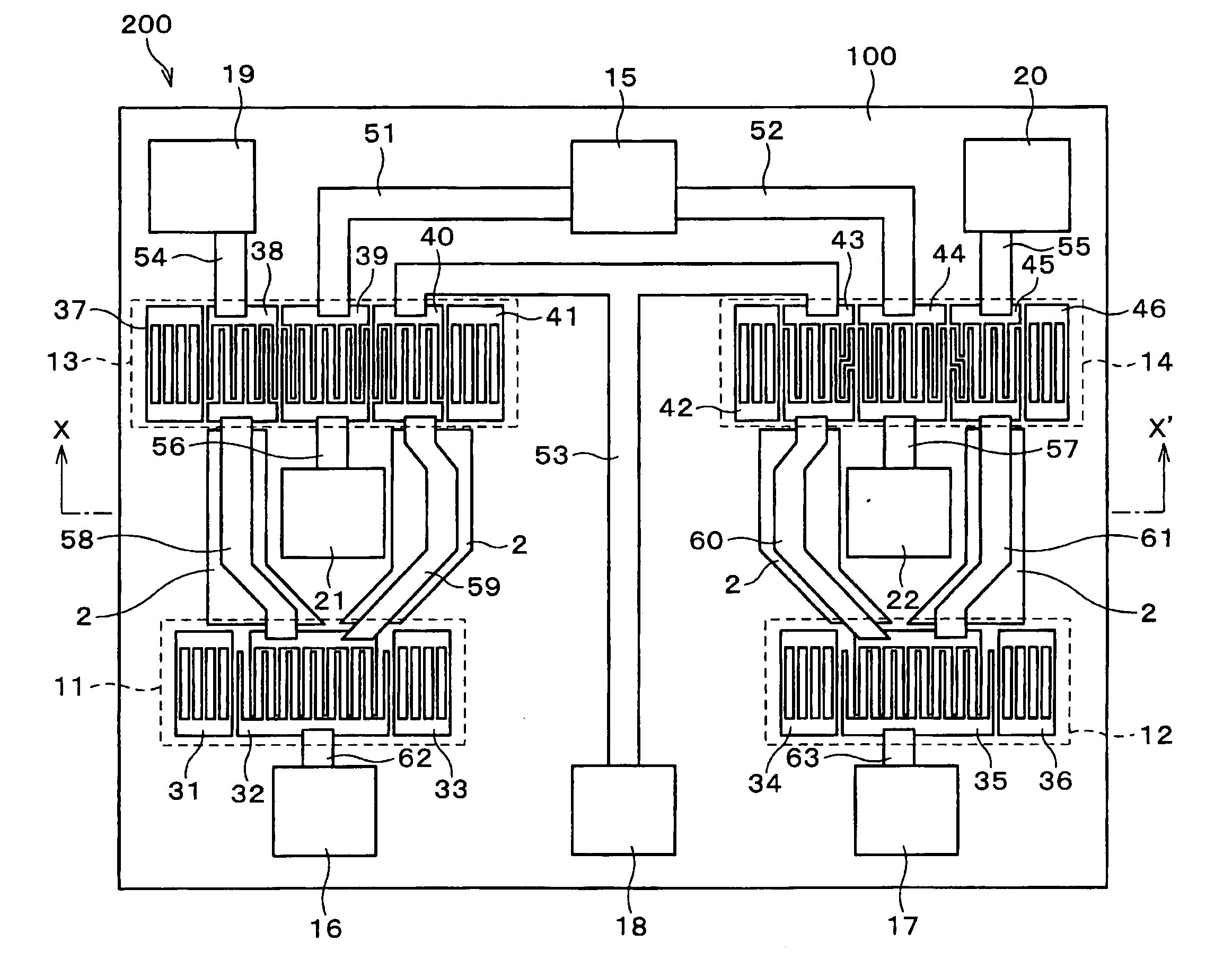
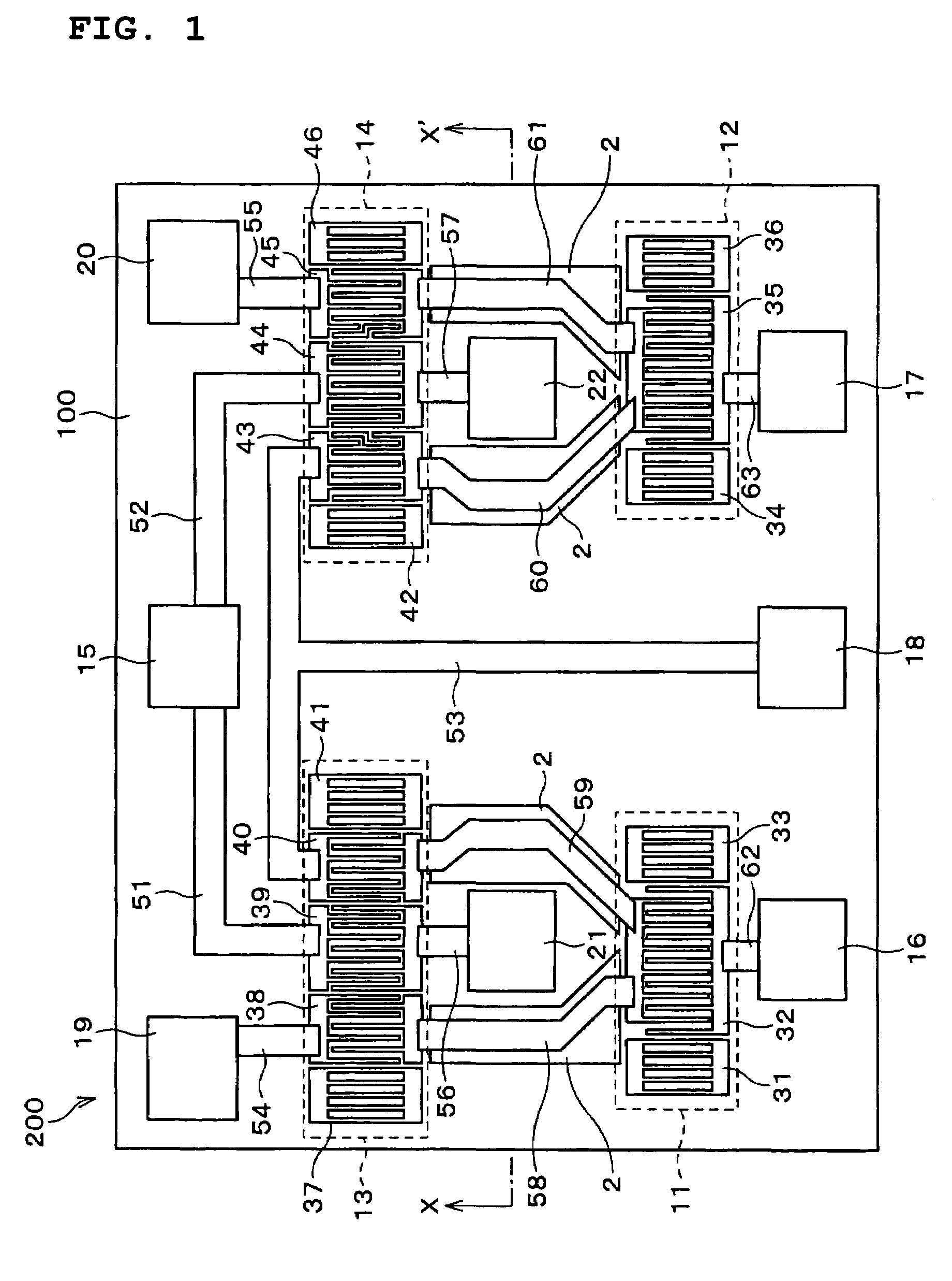
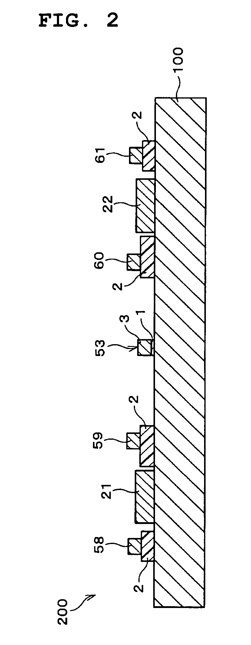
[0088]As shown in FIGS. 1 and 2, a surface acoustic wave (SAW) filter 200 according to a first preferred embodiment includes a first conductor pattern 1, a resin pattern (insulating pattern) 2, and a second conductor pattern 3, which are arranged on a piezoelectric substrate 100. In a direction vertical to the plane of FIG. 1, the piezoelectric substrate 100 is at the lowermost position, and the first conductor pattern 1, the resin pattern 2, and the second conductor pattern 3 are disposed in this order. The piezoelectric substrate 100 is a 38.5° rotated Y-cut X-propagation LiTaO3 single crystal.

[0089]The first conductor pattern 1 includes an aluminum thin-film which is about 200 nm thick. The resin pattern 2 includes a polyimide film which is about 1 μm thick. The second conductor pattern 3 includes two layers of conductive thin-films, in which the lower layer is a nichrome thin-film which is about 200 nm thick and the upper layer is an aluminum thin-film which is about 1000 nm thi...

second preferred embodiment

[0125]FIG. 8 shows a SAW filter 300 according to a second preferred embodiment. FIG. 9 is a cross-sectional view taken along the line Y-Y′ in FIG. 8. In the SAW filter 300 shown in FIG. 8, portions denoted by the same reference numerals as in FIG. 1 have the same function as that in the SAW filter 200. The differences between the SAW filters 300 and 200 are the shape of the resin pattern 2 and the wiring traces. Hereinafter, the different parts will be described.

[0126]A wiring trace 301 is a portion of the second conductor pattern 3 and enables the input pad 15 and the IDT 39 to be electrically continuous. A wiring trace 302 is a portion of the second conductor pattern 3 and enables the input pad 15 and the IDT 44 to be electrically continuous.

[0127]A wiring trace 303 is a portion of the second conductor pattern 3 and enables the IDTs 38 and 32 and the IDTs 40 and 32 to be electrically continuous. A wiring trace 304 is a portion of the second conductor pattern 3 and enables the IDTs...

third preferred embodiment

[0133]FIG. 10 shows a SAW filter 400 according to a third preferred embodiment. FIG. 11 is a cross-sectional view taken along the line Z-Z′ in FIG. 10. The SAW filter 400 is a ladder band-pass filter including three one-terminal-pair SAW resonators 401 to 403 connected in a ladder pattern. The specific operating principles of the ladder filter are known, and thus, they are not described here.

[0134]All of the one-terminal-pair SAW resonators 401 to 403, wiring traces 404 to 409, an input pad 410, an output pad 411, and a ground pad 412 are part of the first conductor pattern 1 disposed on the piezoelectric substrate 100. The one-terminal-pair SAW resonators 401 to 403 are arranged such that the SAW propagation directions thereof are substantially parallel to each other.

[0135]Portions of the wiring traces 404 to 407 at the positions facing each other in a plan view are disposed on the resin pattern 2. A method for manufacturing the SAW filter 400 is not specified. For example, the res...


PUM


Abstract

A surface acoustic wave (SAW) filter includes a piezoelectric substrate. A resin pattern having a permittivity less than that of the piezoelectric substrate and first and second conductor patterns are disposed on the piezoelectric substrate. The first conductor pattern defines two one-terminal-pair SAW resonators and two longitudinally coupled resonator SAW filters. A portion of the second conductor pattern defines wiring traces having different potentials. Portions of the wiring traces facing each other in a plan view are disposed on the resin pattern.

Description

BACKGROUND OF THE INVENTION[0001]1. Field of the Invention[0002]The present invention relates to surface acoustic wave (SAW) filters having an improved transmission characteristic suitable for band-pass filters of communication apparatuses, such as portable phones, and to communication apparatuses including the same.[0003]2. Description of the Related Art[0004]In compact communication apparatuses such as portable phones, band-pass filters having a pass-band of several tens of MHz to several GHz have been commonly used. As an example of the band-pass filters, compact SAW filters have been used.[0005]As shown in FIG. 25, a SAW filter 500 includes a filter element 504 having a reflector 510, interdigital transducers (IDTs) 501 to 503, and a reflector 511, which are arranged along a SAW-propagating direction on a piezoelectric substrate 100. Herein, each of the IDTs 501 to 503 provides an electric signal to a SAW coupling transducer including a pair of comb electrodes engaged with each ...

Claims


Application Information

Patent Timeline
Patent Type & Authority Patents(United States)
IPC IPC(8): H03H9/64H01P1/203H03H9/00H03H9/145
CPCH03H9/0038H03H9/0071H03H9/0085H03H9/6483H03H9/14582H03H9/14588H03H9/009H01P1/203
Inventor SHIBAHARA, TERUHISANAKAHASHI, NORIHIKOWATANABE, HIROKITAKAMINE, YUICHI
Owner MURATA MFG CO LTD
Why Eureka
Try Eureka