
Method for controlling the current intensity of the electric current flowing through an inductive consumer and a corresponding circuit configuration

a technology of inductive consumer and current intensity, which is applied in the direction of process and machine control, magnetic bodies, instruments, etc., can solve the problems of only being able to adjust the supply voltage, the exact adjustment of the current intensity cannot be easily carried out, and the changes in the supply voltage cannot be corrected. , to achieve the effect of reducing the application complexity of the system, simplifying the parameterization of the first controller, and increasing the degree of accuracy

Active Publication Date: 2015-07-23
ROBERT BOSCH GMBH
View PDF21 Cites 4 Cited by
  • Summary
  • Abstract
  • Description
  • Claims
  • Application Information

AI Technical Summary

Benefits of technology

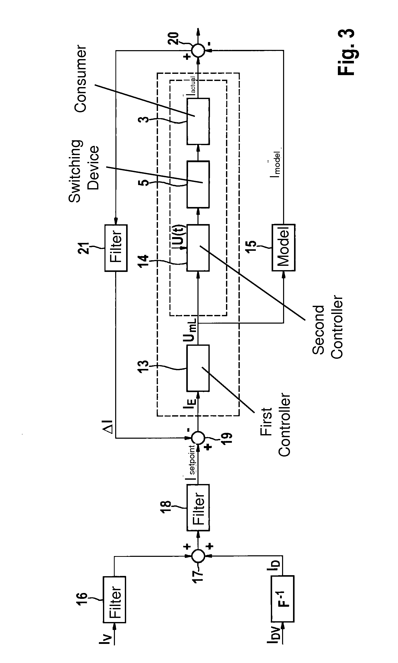
The present invention provides a method for controlling the current intensity of an electric current flowing through an inductive consumer with a higher degree of accuracy than previous methods. This is achieved by determining the mean load voltage during the pulse width modulation period using an input current intensity and a model adapted to the consumer. The input current intensity is set through a controller in order to control the current intensity, and the setpoint current intensity is determined from a predefined setpoint current intensity and the difference between it and the actual current intensity. This approach simplifies the parameterization of the controller and reduces the complexity of the system. The switching device is activated based on the pulse duty factor to compensate for fluctuations of the supply voltage. The method also achieves a minimum hysteresis of the consumer by keeping the element in motion and avoiding sudden changes in the current intensity. The current intensities may be filtered to improve stability.

Problems solved by technology

Due, in particular, to the self-induction of the inductive consumer, the latter exhibits a hysteresis-like behavior, which means that an exact adjustment of the current intensity may no longer be readily carried out due to inaccuracies resulting from the hysteresis-like behavior, so that the actual current intensity of the electric current flowing through the inductive consumer may only be approximately adjusted.
The supply voltage of the power supply, designed, for example, as a battery or a rechargeable battery, is normally superposed, however, by dynamic disturbances, i.e., voltage drops or voltage jumps, for example.
However, this in turn would mean that changes in the supply voltage could only be corrected by a delay resulting from the filtering.
This is a problem, in particular, in the case of voltage jumps to high voltages, because these could cause damage to the consumer.
Instead of or in addition to the limitation of the mean load voltage, the absolute value of the mean load voltage may also be limited.

Method used


Image

  • Method for controlling the current intensity of the electric current flowing through an inductive consumer and a corresponding circuit configuration
  • Method for controlling the current intensity of the electric current flowing through an inductive consumer and a corresponding circuit configuration
  • Method for controlling the current intensity of the electric current flowing through an inductive consumer and a corresponding circuit configuration

Examples


Embodiment Construction

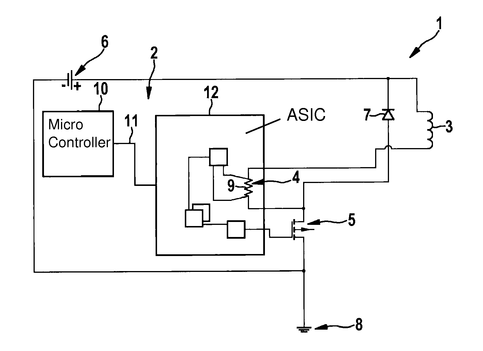
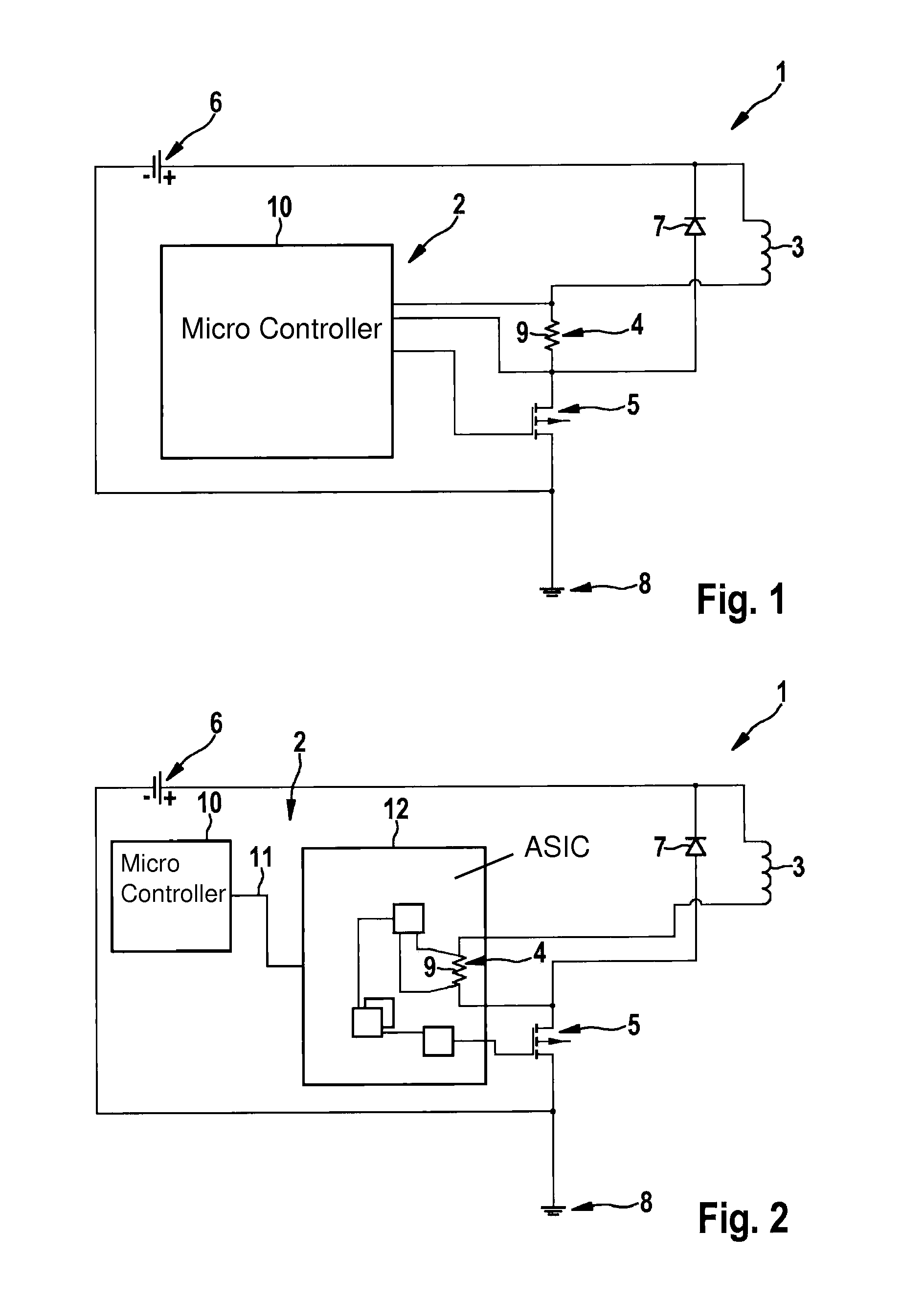
[0033]FIG. 1 shows a circuit configuration 1, which includes a control unit 2, an inductive consumer 3, a current measuring unit 4 and a switching device 5. A power supply 6 is also provided. Connected jointly to the power supply are consumer 3, current measuring unit 4 and switching device 5, these being connected in series to one another. A free-wheeling element 7 in the form of a free-wheeling diode is connected at least in parallel to consumer 3, preferably, however, also in parallel to current measuring unit 4. The cathode of free-wheeling element 7 is connected to a positive pole of power supply 6, whereas the anode of the free-wheeling element is connected either between consumer 3 and current measuring unit 4 or (as depicted here), between current measuring unit 4 and switching device 5. Consumer 3 is present, for example, as a solenoid valve or as a coil of the solenoid valve.

[0034]The side of switching device 5 facing away from consumer 3 is connected to a ground 8. This i...


PUM


Abstract

A method is provided for controlling the current intensity of the electric current flowing through an inductive consumer, the consumer being connected in series to a switching device and a current measuring unit, and in parallel to a free-wheeling element, and the switching device being activated for adjusting the current intensity during a pulse width modulation period. It is provided that a mean load voltage to be set during the pulse width modulation period is determined from an input current intensity with the aid of a first controller, the mean load voltage being set in the pulse width modulation period with the aid of the switching device at the consumer, the mean load voltage or a setpoint load voltage determined with the aid of a second controller from a predefined setpoint current intensity being fed to a model adapted to the consumer, and the input current intensity being ascertained from the difference between the predefined setpoint current intensity and a difference variable between an actual current intensity through the consumer and a model current intensity determined with the aid of the model. A circuit configuration for implementing the method is also provided.

Description

FIELD OF THE INVENTION[0001]The present invention relates to a method for controlling the current intensity of the electric current flowing through an inductive consumer, the consumer being connected in series to a switching device and a current measuring unit, and in parallel to a freewheeling element, and the switching device being activated for adjusting the current intensity during a pulse width modulation period. The present invention also relates to a circuit configuration.BACKGROUND INFORMATION[0002]The inductive consumer is, for example, an actuator or the like, which is used, in particular, in a transmission of a motor vehicle, for example, an automatic transmission. To operate the consumer, the consumer is supplied with electric current, and the behavior of the consumer is capable of being influenced by adjusting the current intensity. The consumer may be present, for example, in the form of a solenoid valve, in which a flow-through cross section for a fluid and, therefore...

Claims


Application Information

Patent Timeline
Patent Type & Authority Applications(United States)
IPC IPC(8): H02M1/08G01R19/00
CPCG01R19/00H02M1/08H02M3/156H01F7/1844H01F2007/1866H01F2007/1888H02M3/1555
Inventor SCHWARZMANN, DIETERMARTINI, MARCOKLEIN, CHRISTIANWIEJA, THOMASMUELLER, BERNDGUENTHER, UWEHERRMANN, ALEXANDERREINHARDT, STEFFENLEIBBRAND, BEATELAMMERS, CHRISTIAN
Owner ROBERT BOSCH GMBH
Learn More