
Thermally activated shape memory spring assemblies for implant expansion

a technology of shape memory and springs, which is applied in the field of springs for implant expansion, can solve the problems of increased trauma to the patient's body, unintended injury to the patient, and infection risk, and achieve the effects of convenient activation of the spring, convenient osteointegration of the implant, and more maneuverability

Active Publication Date: 2015-07-30
TITAN SPINE
View PDF29 Cites 14 Cited by
  • Summary
  • Abstract
  • Description
  • Claims
  • Application Information

AI Technical Summary

Benefits of technology

The patent describes an implant that uses a thermal memory spring to securely hold an item in place and prevent it from moving or expelling. The spring is designed to warm up and expand the implant when placed in a patient's body, and can be adjusted and re-positioned as needed. The implant can also contain bone graft material to facilitate bone growth. The technical effect of this design is that it provides a secure and adjustable implant that reduces the risk of complications and improves the likelihood of successful osteointegration.

Problems solved by technology

Larger and more irregularly shaped implants generally necessitate larger incisions and larger pathway dissections, causing additional trauma to the patient's body and risking unintended injury to the patient.
In addition, such larger incisions and tissue dissection increases the risk of an infection, prolongs recovery time, and may cause additional discomfort in the patient during the post-surgery healing period.
It is desirable to minimize trauma to the body during the implantation procedure, yet there are practical limitations to these efforts insofar as the implant needs sufficient room for insertion and placement.
Often, this manipulation requires significant amounts of time for adjusting the implant until the final extended position is attained.
The additional time required for this process increases cost of the procedure, as well as enhances the risk to the patient for developing an infection or other complications.

Method used


Image

  • Thermally activated shape memory spring assemblies for implant expansion
  • Thermally activated shape memory spring assemblies for implant expansion
  • Thermally activated shape memory spring assemblies for implant expansion

Examples


Embodiment Construction

[0062]Various terms relating to aspects of the present invention are used throughout the specification and claims. Such terms are to be given their ordinary meaning in the art, unless otherwise indicated. Other specifically defined terms are to be construed in a manner consistent with the definition provided herein.

[0063]As used herein, the singular forms “a,”“an,” and “the” include plural referents unless expressly stated otherwise.

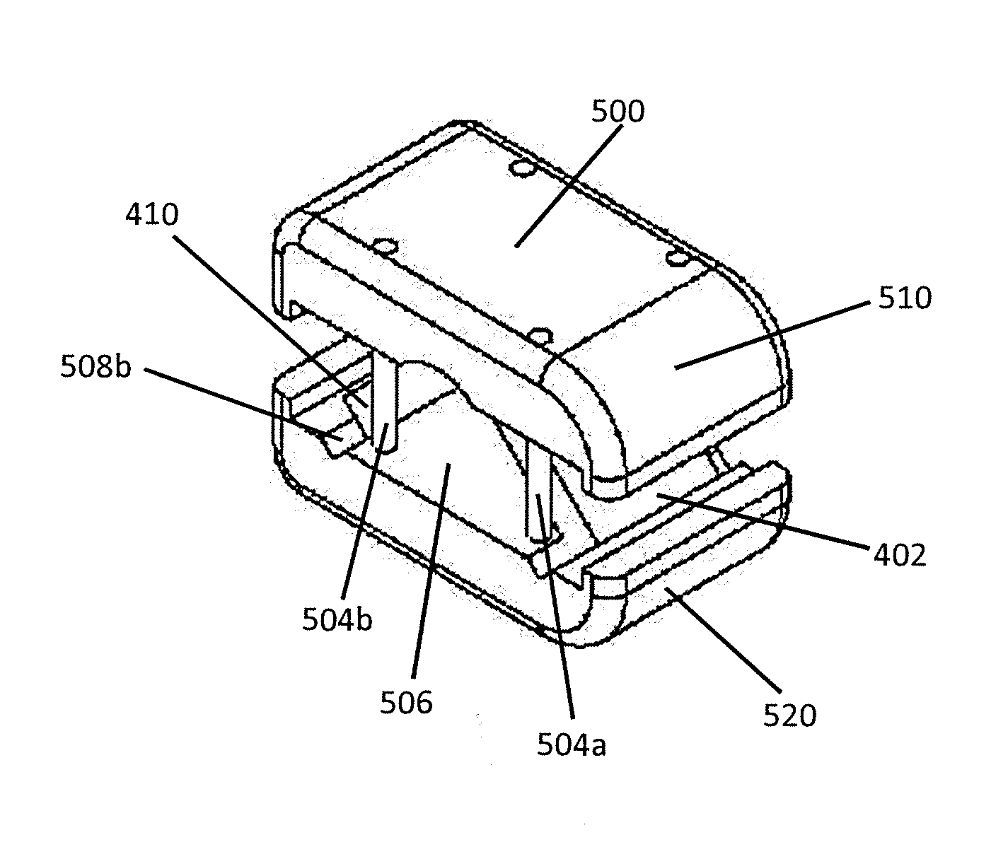
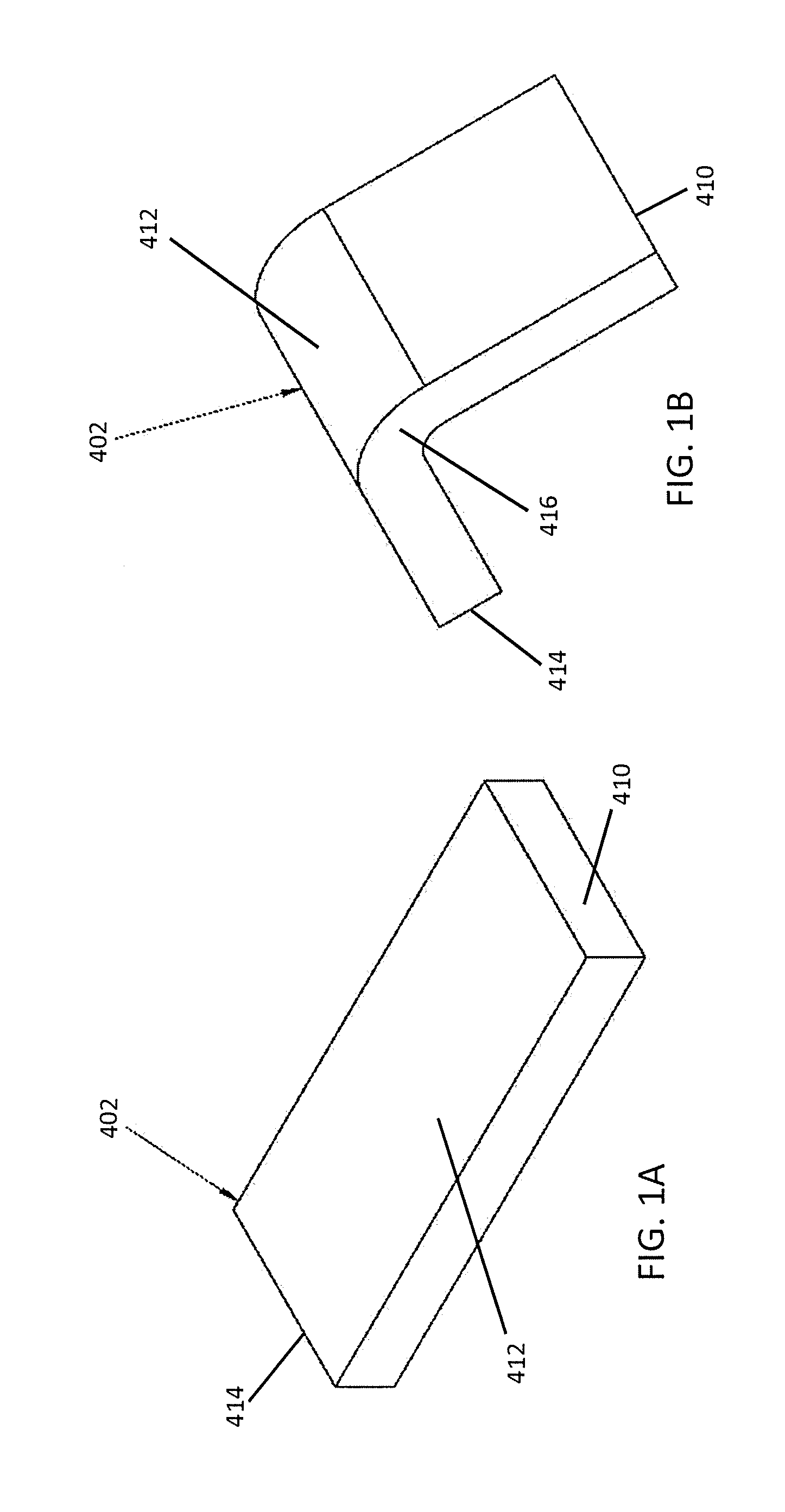
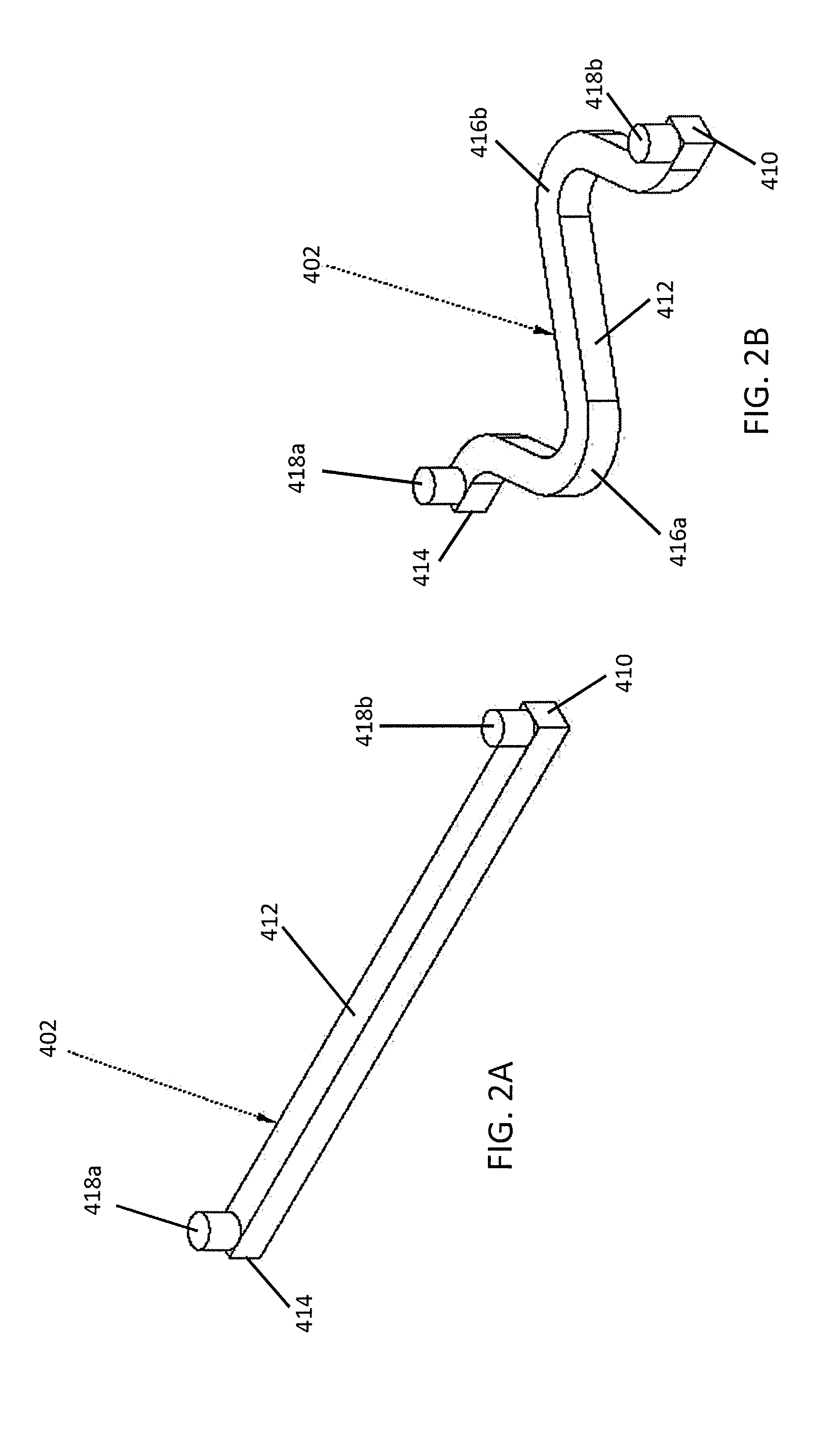
[0064]The invention features mechanisms for expanding implants following their insertion into the body. A foundational feature is an shape-memory spring 402 comprised of a material that has a thermal shape memory. For example, certain metals, including Nitinol (a nickel and titanium alloy) may be shaped into a desired shape or state or configuration at very high temperatures, then forcibly straightened, relaxed, or held in a different shape or state or configuration at room temperature. When the metals are exposed to temperatures greater than room temper...


PUM


Abstract

Thermal memory springs may form arches, or have coils or spring arms and truss arms that expand from a relaxed state when the thermal memory springs warm to a temperature that is about the body temperature of a human being. The thermal memory springs may be used to expand interbody implants from a compact state into an expanded state once the implant has been inserted into the desired location within the body and the thermal memory springs that form a part of the implant warms to body temperature. Ends of the expanded thermal memory spring may contact a bone surface, thereby being an anti-expulsion edge.

Description

FIELD OF THE INVENTION[0001]The invention relates generally to springs for expansion of implants, especially spinal implants. In particular, the invention relates to springs comprising a material that has a thermal shape memory, which expand or conform to a predetermined shape at body temperature, as well as methods of using implants comprising such springs, including for spinal fusion applications.BACKGROUND OF THE INVENTION[0002]Various publications, including patents, published applications, technical articles and scholarly articles are cited throughout the specification. Each of these cited publications is incorporated by reference herein, in its entirety and for all purposes.[0003]Orthopedic implants come in many different shapes and sizes to accommodate different sizes and needs of particular patients. For implantation, an incision at or near the site of implantation, or otherwise conducive for implantation, is made in the patient, with additional tissue dissected to create a ...

Claims


Application Information

Patent Timeline
IPC IPC(8): A61F2/44
CPCA61F2/4455A61F2002/30476A61F2002/30092A61F2002/30565A61F2/44A61F2002/30556A61F2002/30579A61F2/447A61F2002/30131A61F2002/30176A61F2002/30225A61F2002/30383A61F2002/30471A61F2002/30484A61F2002/30515A61F2002/30538A61F2002/3055A61F2002/30566A61F2002/30571
Inventor PATTERSON, CHAD J.GARDNER, ERIC M.
Owner TITAN SPINE
Learn More