Working vehicle

Active Publication Date: 2015-07-30
KUBOTA LTD
View PDF15 Cites 14 Cited by
  • Summary
  • Abstract
  • Description
  • Claims
  • Application Information

AI Technical Summary

Benefits of technology

[0009]As effects of the disclosure,

Problems solved by technology

However, JP 5285488 B2 does not describe the configuration for taking out power from the engine from the fro

Method used


Image

  • Working vehicle
  • Working vehicle
  • Working vehicle

Examples


first embodiment

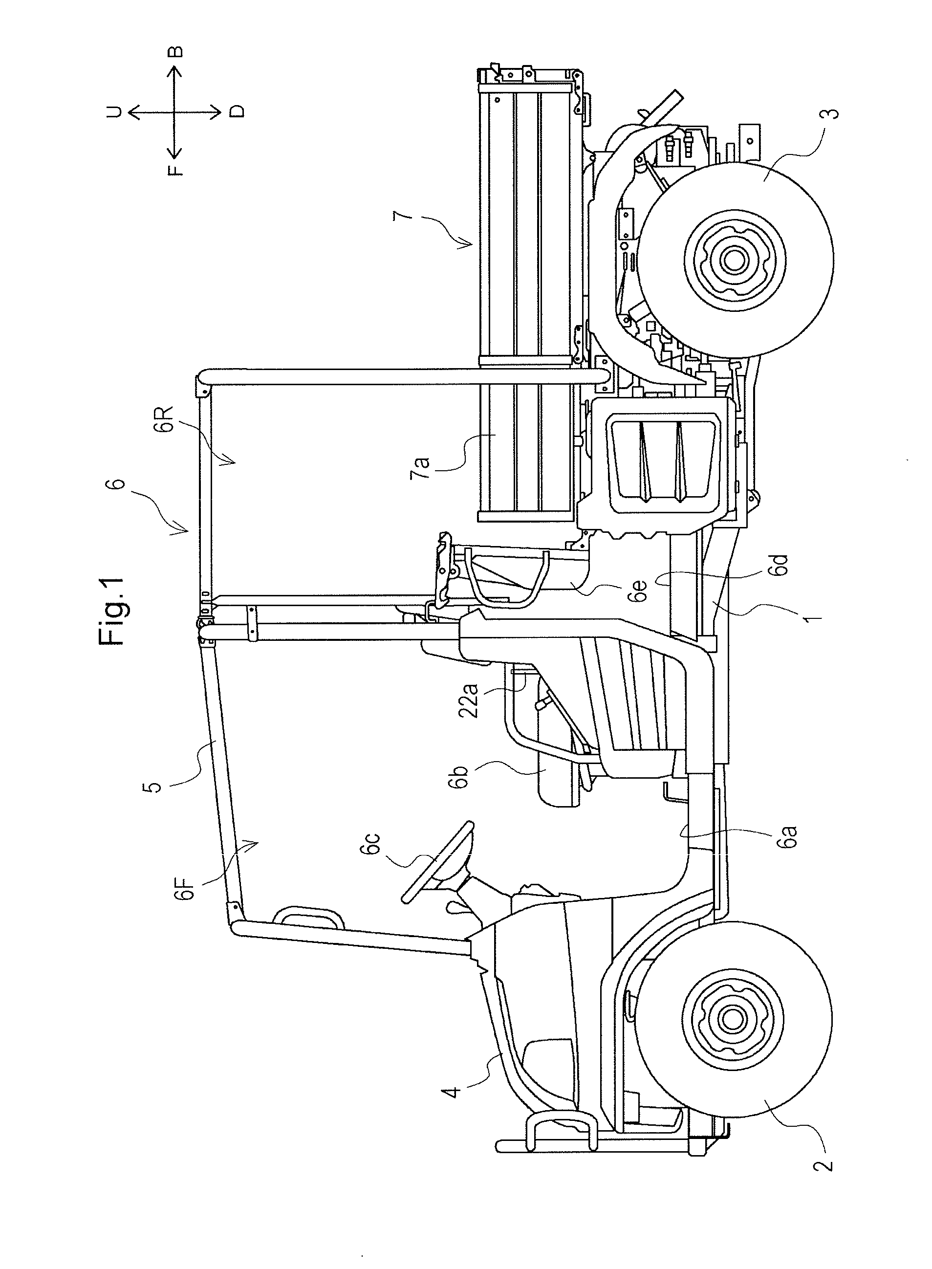
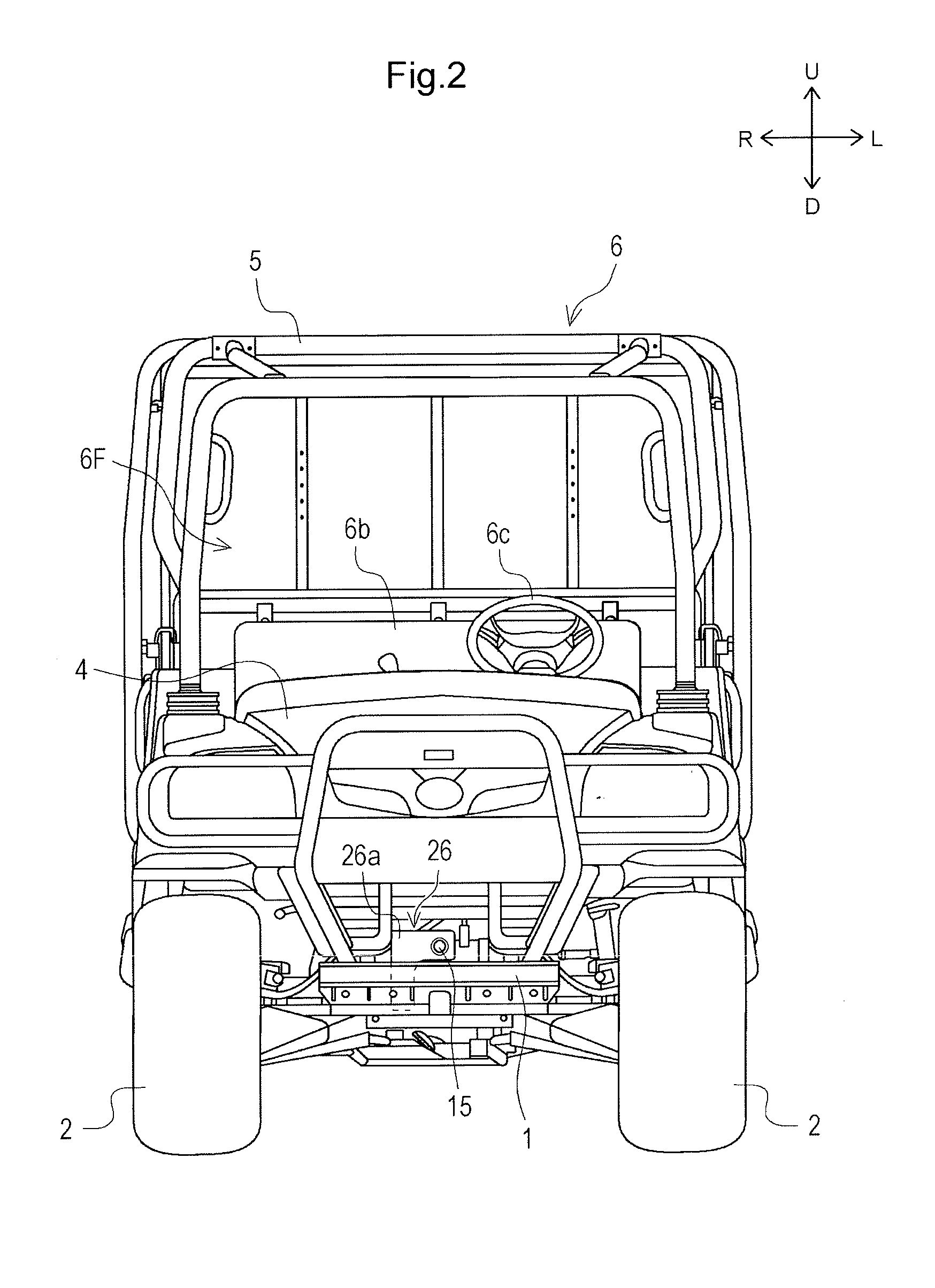
[0033]An overall configuration of a working vehicle according to one embodiment (first embodiment) of the disclosure is described hereinafter with reference to FIG. 1 and FIG. 2.

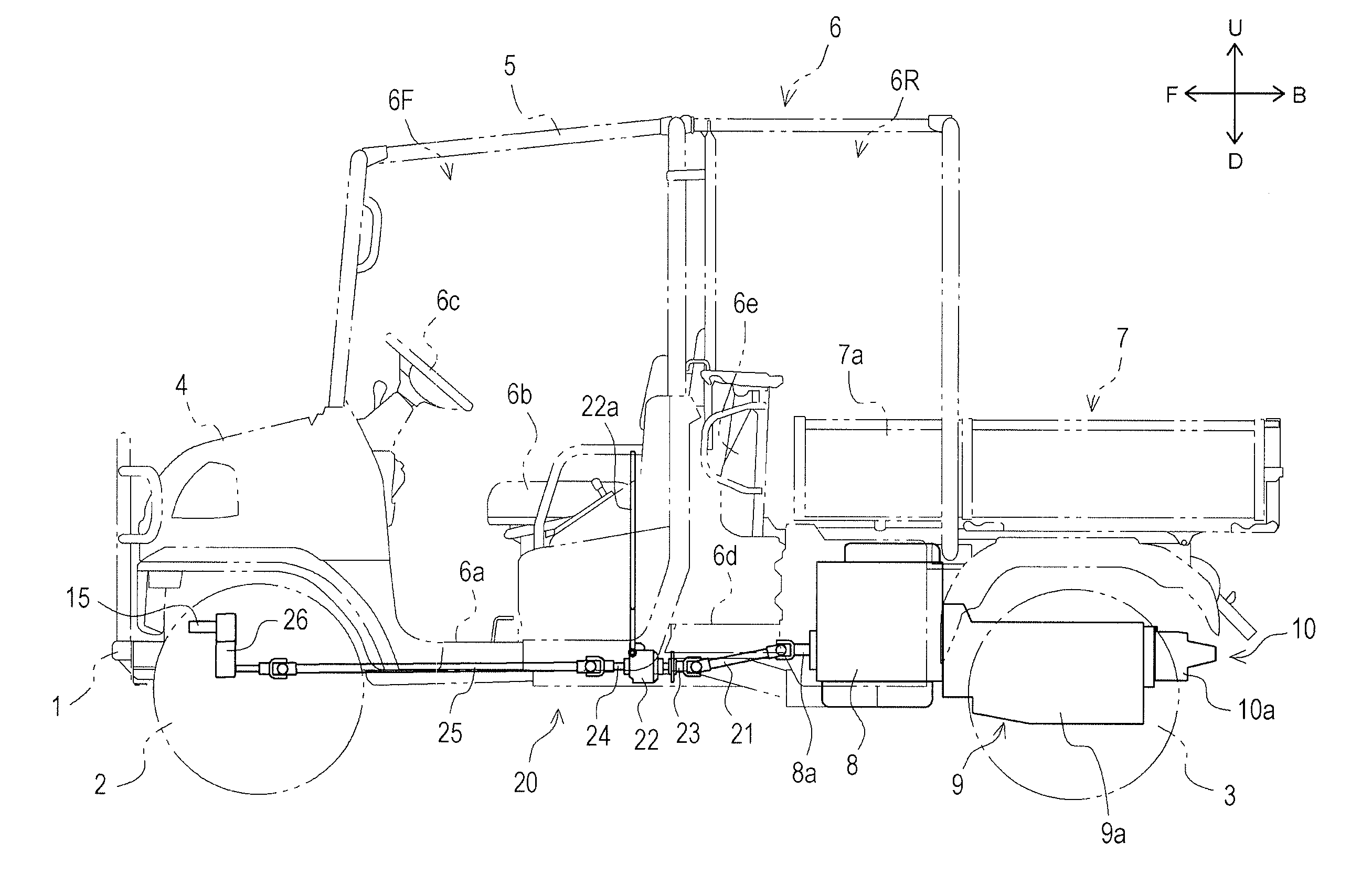
[0034]The working vehicle includes a main frame 1 as a main structural body of a vehicle body thereof. The main frame 1 is formed by combining pipe members, plate members and the like and extends in the longitudinal direction. A front portion of the main frame 1 is supported on a pair of left and right front wheels 2, and a rear portion of the main frame 1 is supported on a pair of left and right rear wheels 3. The front wheels 2 and the rear wheels 3 are drivable wheels (drive wheels). A front cover 4 is mounted on the front portion of the main frame 1 so as to cover the main frame 1 from above. A protective frame 5 is disposed above an intermediate portion of the main frame 1 in the longitudinal direction. A driving operation part 6 on which an operator rides is formed in an approximately rectangular paral...

second embodiment

[0085]Firstly, a working vehicle is described with reference to FIG. 11.

[0086]In the working vehicle according to the first embodiment, as shown in FIG. 11A, the mechanical power transmission mechanism 20 includes the rear transmission shaft 21, the clutch input shaft 23, the clutch output shaft 24, and the front transmission shaft 25. However, in the working vehicle according to the second embodiment (see FIG. 11B), a mechanical power transmission mechanism 20 includes two shafts (a rear transmission shaft 21 and a second transmission shaft 31). In this case, a second universal joint 27b and a fourth universal joint 27d are connected to each other by the second transmission shaft 31 in place of the clutch input shaft 23, the clutch output shaft 24 and the front transmission shaft 25 according to the first embodiment. Due to such a configuration, compared to the working vehicle according to the first embodiment, one universal joint (the third universal joint 27c) can be eliminated ...

third embodiment

[0087]Next, a working vehicle is described with reference to FIG. 12A.

[0088]In the working vehicle according to the third embodiment, a mechanical power transmission mechanism 20 includes one shaft (a third transmission shaft 32). The third transmission shaft 32 is disposed in an extending manner from a rear portion to a front portion of a vehicle body of the working vehicle. In this case, a first universal joint 27a and a fourth universal joint 27d are connected to each other by the third transmission shaft 32. Due to such a configuration, compared to the working vehicle according to the first embodiment, two universal joints (the second universal joint 27b and the third universal joint 27c) can be eliminated and hence, the structure of the mechanical power transmission mechanism 20 can be simplified.


PUM


Abstract

Provided is a working vehicle which includes: an engine disposed on a rear portion of a vehicle body; a gear-type transmission and an HST which are disposed on the rear portion of the vehicle body; a load-carrying platform disposed above at least one of the engine, the gear-type transmission and the HST; a driving operation part disposed in front of the load-carrying platform and allowing an operator to ride thereon; a PTO shaft mounted on a front portion of the vehicle body and being capable of taking out power to the outside of the working vehicle; and a mechanical power transmission mechanism for transmitting the power from the engine which is before the power is transmitted with a speed change by the gear-type transmission and the HST to the PTO shaft by extending below the driving operation part.

Description

TECHNICAL FIELD[0001]The disclosure relates to a technique of a working vehicle provided with a load-carrying platform disposed on a rear portion of a vehicle body.BACKGROUND ART[0002]Conventionally, there has been known a technique of a working vehicle provided with a load-carrying platform disposed on a rear portion of a vehicle body. For example, JP 5285488 B2 discloses such a technique.[0003]JP 5285488 B2 discloses a working vehicle which can travel by transmitting power from an engine to a front wheel and a rear wheel by means of a traveling power transmission device. An operator can desirably move or perform transport operation using such a working vehicle.[0004]On the other hand, with respect to such a working vehicle, there has been a demand for a working vehicle where various working devices (such as a snow blower which performs snow removing operation and a mower which performs mowing operation) driven by rotational power from an engine (hereinafter simply referred to as “...

Claims


Application Information

Patent Timeline
IPC IPC(8): B60K17/28B60K5/00
CPCB60K5/00B60K17/28B60K5/02B60K2005/003B60Y2200/86
Inventor MURAKAWA, MASATAKENAKAJI, MASARUNOSE, TATSUYAFUJII, TAKASHI
Owner KUBOTA LTD
Why Eureka
Try Eureka