Actuator for an electric parking brake system

Active Publication Date: 2015-07-30
JOHNSON ELECTRIC INTERNATIONAL AG
View PDF6 Cites 22 Cited by
  • Summary
  • Abstract
  • Description
  • Claims
  • Application Information

AI Technical Summary

Benefits of technology

[0020]In summary, the actuator of the present electric parking brake system utilizes a planetary gear

Problems solved by technology

However, the conventional actuator requires tight tolerance component fabrication and is difficult to assemble.
Theref

Method used


Image

  • Actuator for an electric parking brake system
  • Actuator for an electric parking brake system
  • Actuator for an electric parking brake system

Examples


Embodiment Construction

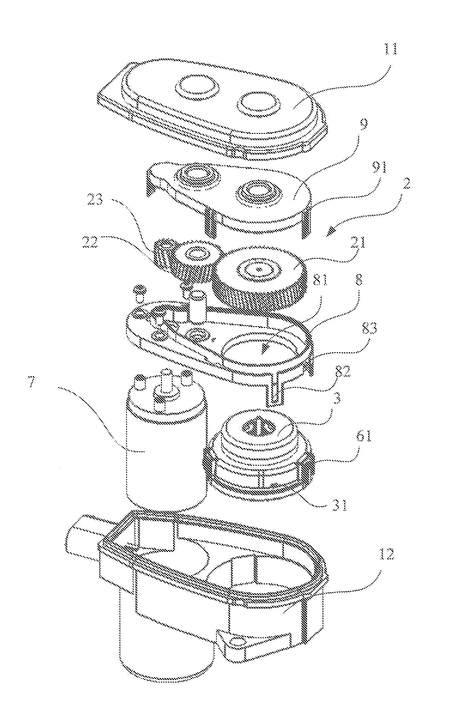
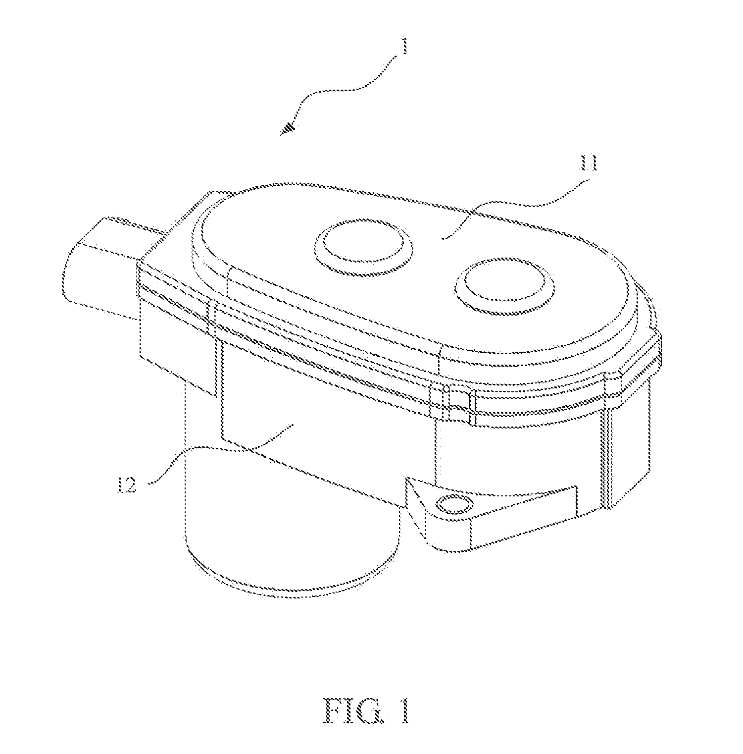
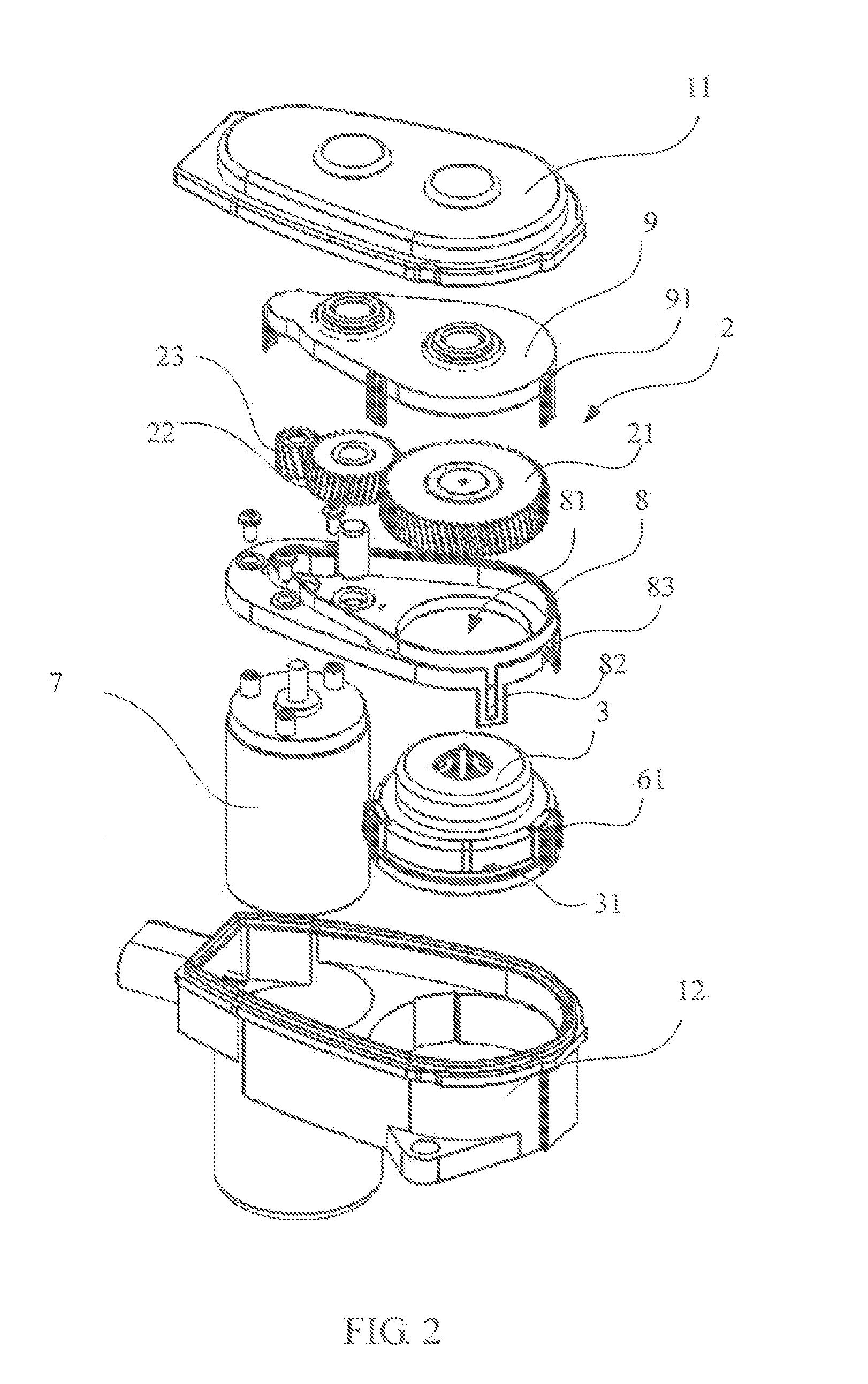
[0030]Referring to FIGS. 1 to 3, an actuator 1 for an electric parking brake system of the present invention includes an outer housing, an electric motor 7, a planetary gear train, and at least one gear 2. In the present embodiment, the outer housing includes an end cover 11 and a housing body 12 that cooperatively house the electric motor, planetary gear train and at least one gear 2 there between. The at least one gear and the planetary gear train form a speed reduction mechanism connecting the motor to the output of the actuator. The at least one gear 2 includes a first gear 21, a second gear 22, and a third gear 23 that are sequentially meshed. The third gear 23 is fixed to the shaft of the motor. The motor drives the planetary gear train through the sequentially meshed second gear 22 and the first gear 21. Power of the motor is transmitted through the speed reduction mechanism to a parking brake caliper (not shown) to brake the car.

[0031]As shown in FIG. 2 and FIG. 3, the outer...


PUM


Abstract

An actuator for an electric parking brake system has an outer housing. A planetary gear train and an electric motor are disposed in the outer housing. At least one gear connects the motor to the planetary gear train. The planetary gear train comprises a multi-stage planetary gear mechanism. A gear housing accommodates the planetary gear mechanism. The planetary gear train further comprises a centering pin extending through the gear mechanism, such that the planetary gear mechanism rotates about the centering pin. Each stage has a sun gear, a ring gear, a plurality of planet gears meshed with the sun gear and ring gear, and a planet carrier rotatably supporting the planet gears.

Description

CROSS REFERENCE TO RELATED APPLICATIONS[0001]This non-provisional patent application claims priority under 35 U.S.C. §119(a) from Patent Application No. 201410041164.9 filed in The People's Republic of China on Jan. 27, 2014, the entire contents of which are hereby incorporated by reference.FIELD OF THE INVENTION[0002]This invention relates to an electric parking brake system and in particular, to an actuator for use in an electric parking brake system.BACKGROUND OF THE INVENTION[0003]A parking brake system of a car is used to keep the car motionless when it is parked. The traditional parking brake system is hand-operated and is commonly referred to as the “handbrake”. When starting a car equipped with a handbrake on a slope, the driver needs to manually release the handbrake in coordination with the accelerator and clutch (if used). The smooth use of the handbrake in such circumstances requires skill by the driver.[0004]With the development of technology, electric parking brake (EP...

Claims


Application Information

Patent Timeline
IPC IPC(8): B60T7/08B60T13/74B60T7/12
CPCB60T7/085B60T13/746B60T7/122B60T13/741F16D2121/24
Inventor QI, FA YUNLI, LI NANNIE, JIN ANQIN, RUI FENG
Owner JOHNSON ELECTRIC INTERNATIONAL AG
Why Eureka
Try Eureka