Control device and control method for internal combustion engine

a control device and control method technology, applied in the direction of electric control, machines/engines, output power, etc., can solve the problems of not being able to discriminate a variation in the cam phase and not being able to execute accurate control, and achieve the effect of accurate fail-safe control

Inactive Publication Date: 2015-07-30
TOYOTA JIDOSHA KK
View PDF9 Cites 13 Cited by
  • Summary
  • Abstract
  • Description
  • Claims
  • Application Information

AI Technical Summary

Benefits of technology

[0008]The invention provides a control device and control method for an internal combustion engine including an intake-side variable valve timing mechanism, which achieves accurate fail-safe control while a cam signal is substituted for a crank signal in the event of a failure in a crank position sensor.
[0020]According to the invention, it is possible to execute accurate fail-safe control on the basis of the signal from the cam position sensor instead of the signal from the failed crank position sensor.

Problems solved by technology

However, if a signal is no longer output from the crank position sensor due to a broken wire, or the like, it may not be able to discriminate a variation in the cam phase even when the cam phase varies.
Therefore, if the position of the VVT mechanism is, for example, displaced by reaction at the time when the intake valve is actuated in the event of occurrence of the above-described failure and, as a result, the cam phase has varied, it may not be able to execute accurate control even when the signal from the rotation sensor of the VVT mechanism is substituted for the crank signal as in the case of JP 2006-214386 A. This also applies to the case where the signal from the cam position sensor (cam signal) is substituted for the crank signal.

Method used


Image

  • Control device and control method for internal combustion engine
  • Control device and control method for internal combustion engine
  • Control device and control method for internal combustion engine

Examples


Embodiment Construction

[0032]Hereinafter, an embodiment of the invention will be described with reference to the accompanying drawings.

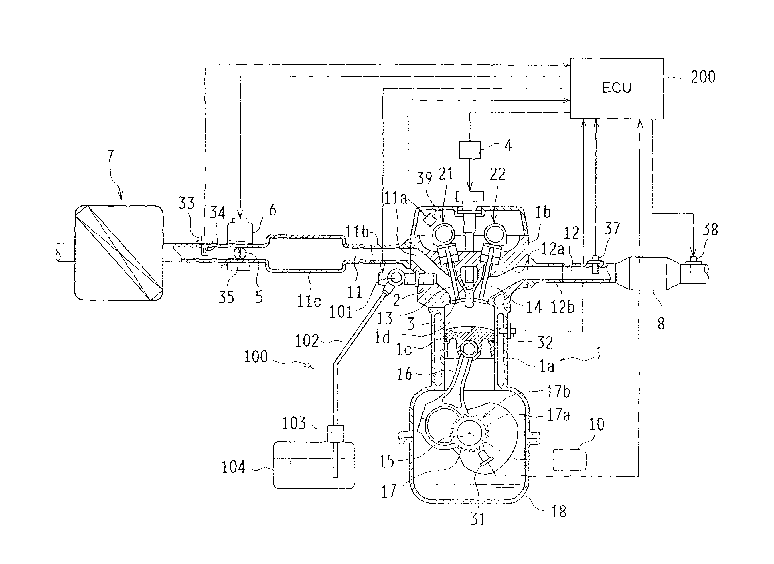
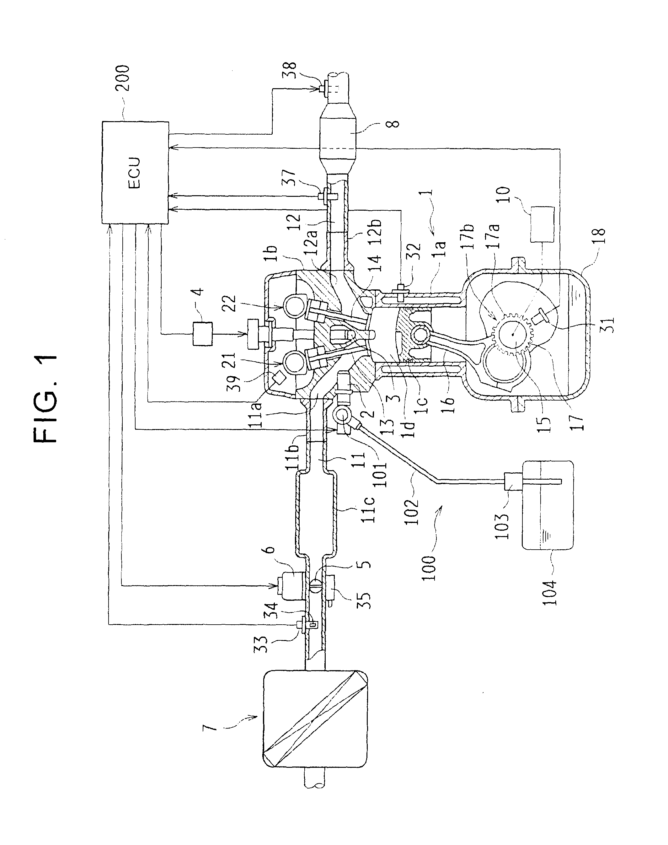
[0033]An internal combustion engine (hereinafter, also referred to as engine) according to the present embodiment will be described with reference to FIG. 1. The engine 1 shown in FIG. 1 is a four-cylinder gasoline engine mounted on a vehicle. In the engine 1, pistons 1c are respectively accommodated in four cylinders (only one cylinder is shown in FIG. 1) formed in a cylinder block 1a so as to reciprocally move up and down. A water jacket is formed in the cylinder block 1a so as to surround those four cylinders, and a coolant temperature sensor 32 is arranged so as to detect the temperature of engine coolant (coolant).

[0034]The reciprocal motions of the pistons 1c in the four cylinders each are converted to the rotational motion of a crankshaft 15 via a corresponding one of connecting rods 16. The crankshaft 15 is coupled to a transmission (not shown) via a torque convert...


PUM


Abstract

A control device for an internal combustion engine includes an intake-side variable valve timing mechanism and a controller. The intake-side variable valve timing mechanism is configured to continuously advance or retard a phase of a cam that actuates an intake valve. The controller is configured to actuate the intake-side variable valve timing mechanism toward a retardation side and position the intake-side variable valve timing mechanism at a prescribed position, and execute fail-safe control on the basis of a signal from a cam position sensor instead of a signal from the crank position sensor, when it is determined that there is a failure in a crank position sensor of the internal combustion engine.

Description

BACKGROUND OF THE INVENTION[0001]1. Field of the Invention[0002]The invention relates to a control device and control method for an internal combustion engine mounted on a vehicle, or the like, and, more particularly, to a control device and control method for an internal combustion engine that includes a variable valve mechanism that is able to change the operation timing of an intake valve.[0003]2. Description of Related Art[0004]Internal combustion engines mounted on vehicles, or the like, increasingly employ a variable valve timing (VVT) mechanism that allows the operation timing of an intake valve to be variable. For example, Japanese Patent Application Publication No. 2006-214386 (JP 2006-214386 A) describes a configuration that an output shaft of an electric motor is coupled to a camshaft that actuates an intake valve and then an intake-side cam phase is continuously advanced or retarded through control over the rotation speed of the electric motor.[0005]In JP 2006-214386 A, ...

Claims


Application Information

Patent Timeline
Patent Type & Authority Applications(United States)
IPC IPC(8): F02D13/02F02D41/04
CPCF02D41/04F02D13/0234F02D41/009F02D41/222F02D13/0238F02D2041/001F02D2041/227Y02T10/40F01L1/352F01L2001/0537F01L2250/02F01L2800/12F01L2820/041F01L2820/042Y02T10/12
Inventor NOMURA, MITSUHIRO
Owner TOYOTA JIDOSHA KK
Why Eureka
Try Eureka