Service data record system and POS system with the same

a service data and record system technology, applied in the field of service data record systems, can solve the problems of difficult repair process, difficult for users or service engineers to readily identify the failed component(s) among the large amount of components, and take a long time for troubleshooting

Active Publication Date: 2015-07-30
FLYTECH TECH
View PDF22 Cites 10 Cited by
  • Summary
  • Abstract
  • Description
  • Claims
  • Application Information

AI Technical Summary

Benefits of technology

[0018]In one embodiment, the electronic device further includes a control unit, which is electrically connected with the plural electronic units and receives the electronic data set from the plural electronic units. The service data record system further includes a storage unit. The micro processing unit is electrically connected with the control unit and the storage unit. The control unit sifts out the at least partial data from the electronic data set and transmits the at least partial data to the micro processing unit. The micro processing unit receives the at least partial data of the electronic data set and transmits an entire of the at least partial data to the storage unit and/or the remote monitoring interface. Alternatively, the service data record system further includes a storage unit electrically connected with the control unit, and the electronic data set from the control unit is received by and stored in the storage unit. The micro processing unit is electrically connected with the control unit and the storage unit. The micro processing unit receives and sifts out the electronic data set from the control unit, so that the at least partial data of the electronic data set is transmitted to the remote monitoring interface, and/or the micro processing

Problems solved by technology

However, it leads to some difficulties during the repair process.
For example, if the POS device is abnormal or unable to be booted while being used, it is hard for a user or a service engineer to readily identify the failed component(s) among the large amount of components.
Actually, it takes much time for trouble shooting.
Furthermore, when the service engineer analyzes the POS device 1, it is hard for the service engineer to accurately find out the reason why the component fails only according to the factory data such as the model type, the specification, the manufactured date, etc.
However, the failure detection device disclosed in this patent still has some drawbacks as follows.
Firstly, the BIOS is only suitable for detecting the failed hardware component related to the motherboard.
Whereas, the breakdown status of the display, the hard disk or the peripheral device and the usage information cannot be obtained through the BIOS.
Secondly, if the electronic device is abnormal, the user or the service engineer can only realize which hardware component fails but cannot realize the information about the failed hardware component (e.g. the usage time, the use frequency or the failure rate) through the display module.
Under this circumstance, the service engineer cannot effectively repair the failed hardware component, but may only repair the electronic device by replacing the failed hardware component with a new one.
Thirdly, if the service engineer who i

Method used


Image

  • Service data record system and POS system with the same
  • Service data record system and POS system with the same
  • Service data record system and POS system with the same

Examples


first embodiment

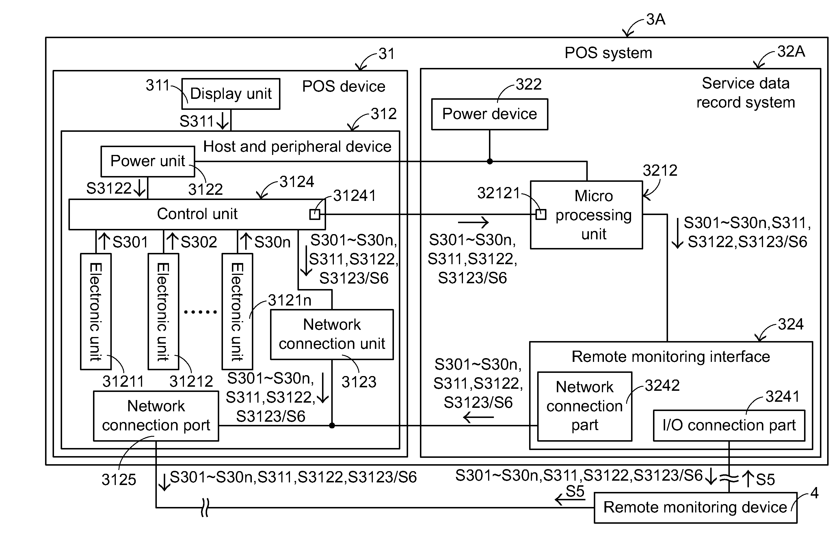
[0043]FIG. 3 is a schematic block diagram illustrating a POS system according to the present invention. As shown in FIG. 3, the POS system 3A comprises a POS device 31 and a service data record system 32A. The POS device 31 comprises a display unit 311 and a host and peripheral device 312. The host and peripheral device 312 comprises plural electronic units 31211˜3121n, a power unit 3122, a network connection unit 3123 and a control unit 3124. The power unit 3122 is used to supply electricity to the POS device 31 in operation. Moreover, each of the electronic units 31211˜3121n provides a specified function. For example, the specified function may be executed to calculate and store the merchandise information such as the quantity, the price, the stock, the gross profit and etc. Moreover, the cashier can watch the merchandise information displayed on the display unit 311.

[0044]In this embodiment, these electronic units 31211˜3121n include a central processing unit (CPU), a mother boar...

third embodiment

[0072]Consequently, the pre-designated event data S4 sifted by the micro processing unit 3212 may be transmitted to and displayed on the terminal display 323. The working principles of the terminal display 323 are similar to those of the third embodiment, and are not redundantly described herein.

[0073]FIG. 9 is a schematic block diagram illustrating a POS system according to a seventh embodiment of the present invention. The components of the POS system 3G that are similar to those of fifth embodiment are designated by identical numeral references, and the detailed descriptions thereof are omitted. In comparison with the fifth embodiment, the action of sifting out the electronic data sets S301˜S30n, S311, S3122 and S3123 is implemented by the control unit 3124 of the POS device 31. Similarly, the control unit 3124 sifts out the desired electronic data S4 by judging whether the electronic data of the electronic data sets S301˜S30n, S311, S3122 and S3123 comply with the pre-designated...


PUM


Abstract

A service data record system and a POS system with the service data record system are provided. The service data record system transmits a data of an electronic device to a remote monitoring device. The electronic device includes plural electronic units and a power unit. The service data record system includes a power device, a remote monitoring interface and a micro processing unit. The micro processing unit is connected with the electronic device, the remote monitoring interface and the power device. By the micro processing unit, the electronic data set of the electronic unit may be externally transmitted to the remote monitoring device. Moreover, the pre-designate event of the electronic device may be externally transmitted to the remote monitoring device. According to the pre-designate event, it is convenient for a service engineer to make the preparation before repair or maintenance.

Description

FIELD OF THE INVENTION[0001]The present invention relates to a service data record system, and more particularly relates to a service data record system for an electronic device and a POS system with the service data record system.BACKGROUND OF THE INVENTION[0002]A point of sale device, also referred as a point of service device or a POS device, is a widely used electronic device in retail industry nowadays, and is mainly used for managing products and the customer information. Generally, the POS device is usually installed on a cashier desk in a convenience store, a shop or a supermarket for displaying the information and the sum of price of merchandise purchased by consumers. Consequently, it is convenient for a cashier to operate the counting task and avoid errors that may be generated in the checkout process.[0003]Please refer to FIG. 1, which is a schematic perspective view of a conventional POS device. The POS device 1 comprises a screen body 11, a bracket base 12 and a host c...

Claims


Application Information

Patent Timeline
IPC IPC(8): G06Q10/00H04L12/26G06Q20/20
CPCG06Q10/20H04L43/065G06Q20/202G07G1/0018G07G1/12G07F9/026G06F11/0748G06F11/0784G06F11/3072G06F11/0778
Inventor LAM, TAI-SENGLEE, HSIAO-HUITSAI, SHUEI-JIN
Owner FLYTECH TECH
Why Eureka
Try Eureka