Injection-locked phase locked loop circuits using delay locked loops

Active Publication Date: 2015-07-30
SAMSUNG ELECTRONICS CO LTD
View PDF4 Cites 38 Cited by
  • Summary
  • Abstract
  • Description
  • Claims
  • Application Information

AI Technical Summary

Benefits of technology

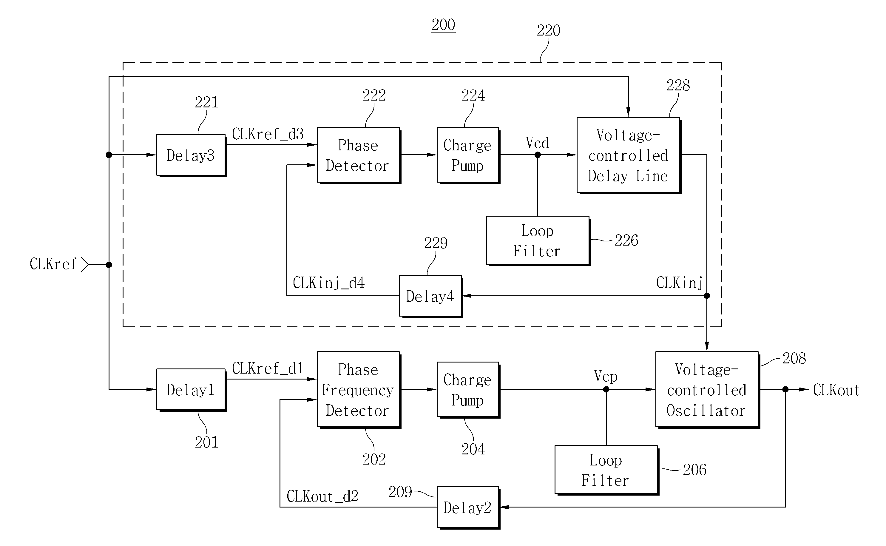
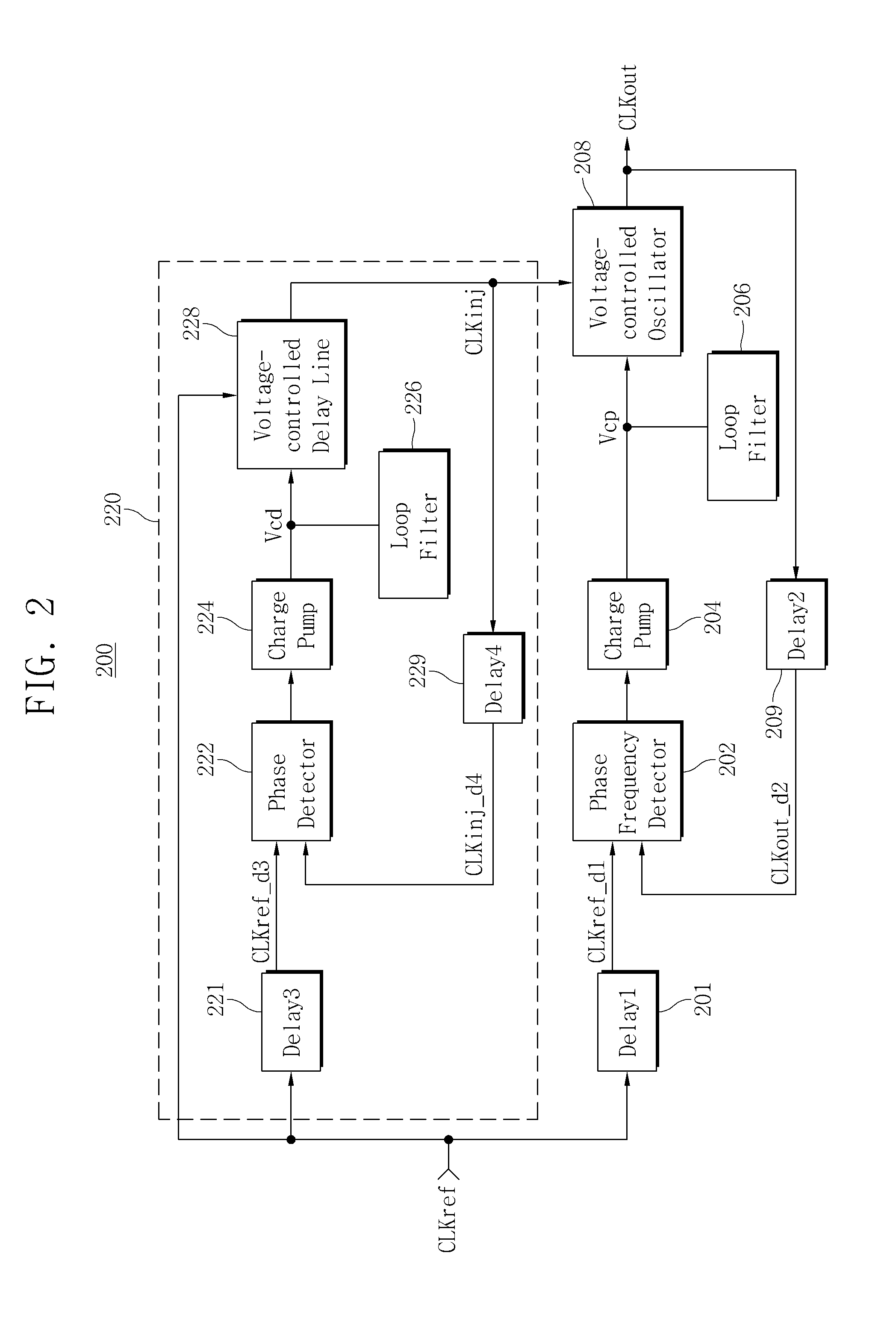
[0027]In accordance with at least one other example embodiment of inventive concepts, a semiconductor memory device includes: a memory core including a plurality of memory cells; a control circuit configured to write data to, and read data stored in, the plurality of memory cells in response to command and address signals; and an internal clock generation circuit configured to generate an internal clock for operation of the semiconductor memory device. The internal clock generation circuit includes: a delay-locked loop (DLL) configured to generate a DLL clock based on a reference clock; and a voltage controlled oscillator configured to generate the internal clock based on the DLL clock and an oscillation controlled voltage, the oscillation controlled voltage being generated based on the reference clock and the internal clock, and a phase of the internal clock being aligned with a phase of the DLL clock.

Problems solved by technology

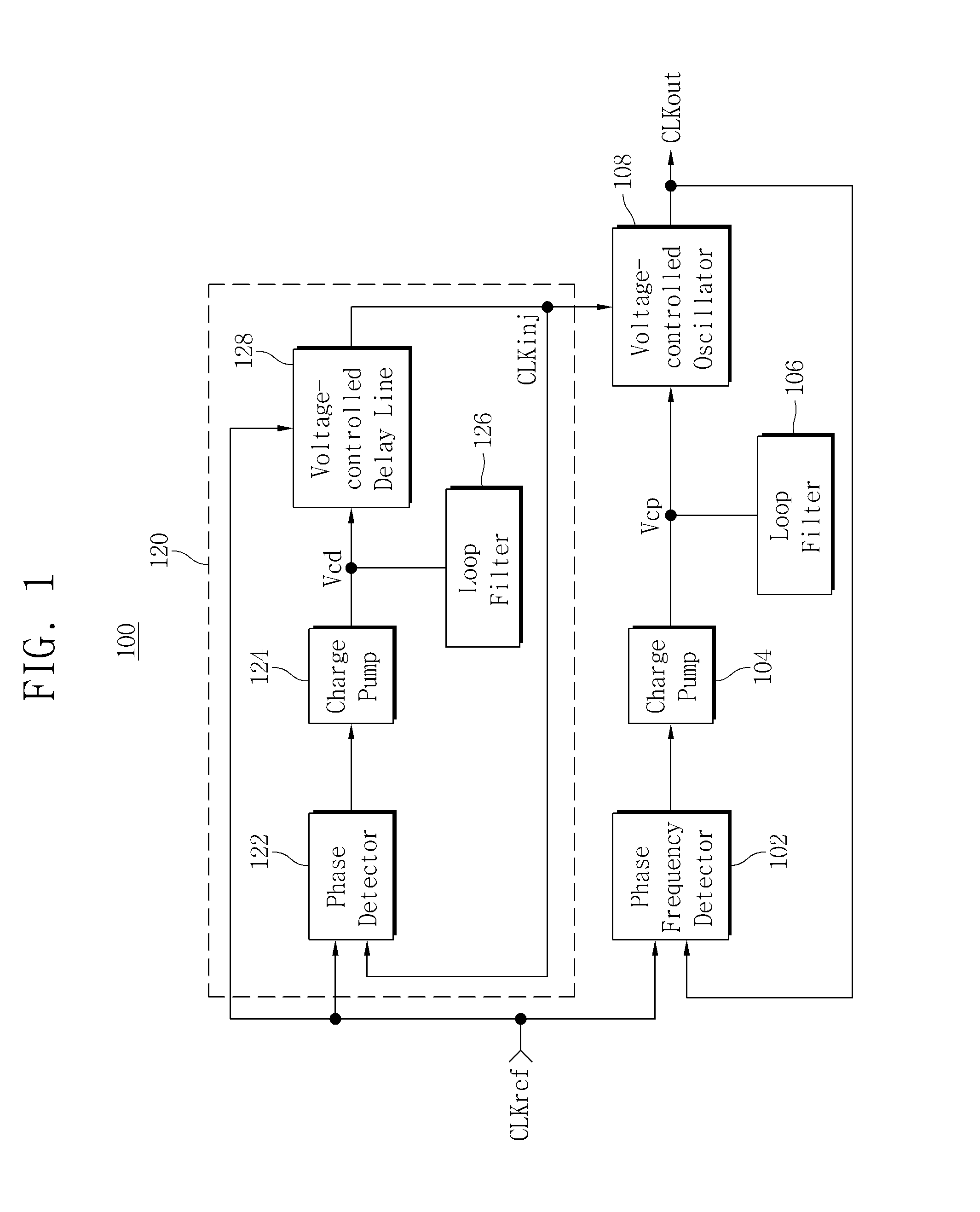
However, since the lock failure of an ILPLL often depends on a phase of an injection signal, the phase of the injection signal must be locked without being affected by changes in process, voltage, temperature, etc.

Method used


Image

  • Injection-locked phase locked loop circuits using delay locked loops
  • Injection-locked phase locked loop circuits using delay locked loops
  • Injection-locked phase locked loop circuits using delay locked loops

Examples


Embodiment Construction

[0044]Example embodiments will now be described more fully with reference to the accompanying drawings. Many alternate forms may be embodied and example embodiments should not be construed as limited to example embodiments set forth herein. In the drawings, like reference numerals refer to like elements.

[0045]It will be understood that, although the terms first, second, etc. may be used herein to describe various elements, these elements should not be limited by these terms. These terms are only used to distinguish one element from another. For example, a first element could be termed a second element, and, similarly, a second element could be termed a first element, without departing from the scope of example embodiments. As used herein, the term “and / or” includes any and all combinations of one or more of the associated listed items.

[0046]While inventive concepts are susceptible to various modifications and alternative forms, specific example embodiments thereof are shown by way o...


PUM


Abstract

An injection-locked phase-locked loop (ILPLL) circuit includes a delay-locked loop (DLL) and an ILPLL. The DLL is configured to generate a DLL clock by performing a delay-locked operation on a reference clock. The ILPLL includes a voltage-controlled oscillator (VCO), and is configured to generate an output clock by performing an injection synchronous phase-locked operation on the reference clock. The DLL clock is injected into the VCO as an injection clock of the VCO.

Description

CROSS-REFERENCE TO RELATED APPLICATION(S)[0001]This application claims priority under 35 U.S.C. §119 to Korean Patent Application No. 10-2014-0010767 filed on Jan. 28, 2014, the disclosure of which is hereby incorporated by reference in its entirety.BACKGROUND[0002]1. Field[0003]Example embodiments of inventive concepts relate to injection-locked phase-locked loop (ILPLL) circuits, and more particularly, to ILPLL circuits using delay-locked loops (DLLs).[0004]2. Description of Related Art[0005]In a conventional source-synchronous system such as a dynamic random access memory (DRAM), an injection-locked phase-locked loop (ILPLL) is used to increase a correlation between a clock and data through a jitter tracking mechanism, and to reduce phase noise of a voltage-controlled oscillator (VCO).[0006]However, since the lock failure of an ILPLL often depends on a phase of an injection signal, the phase of the injection signal must be locked without being affected by changes in process, volt...

Claims


Application Information

Patent Timeline
Patent Type & Authority Applications(United States)
IPC IPC(8): G11C11/4076G11C11/408G11C11/409H03L7/089H03L7/087
CPCG11C11/4076H03L7/0893G11C11/408G11C11/409H03L7/087G11C7/222H03L7/07H03L7/083H03L7/0995
Inventor JOO, HYE-YOONBAE, SEUNG-JUNSOHN, YOUNG-SOOSONG, HO-SUNGIHM, JEONG-DON
Owner SAMSUNG ELECTRONICS CO LTD
Why Eureka
Try Eureka