

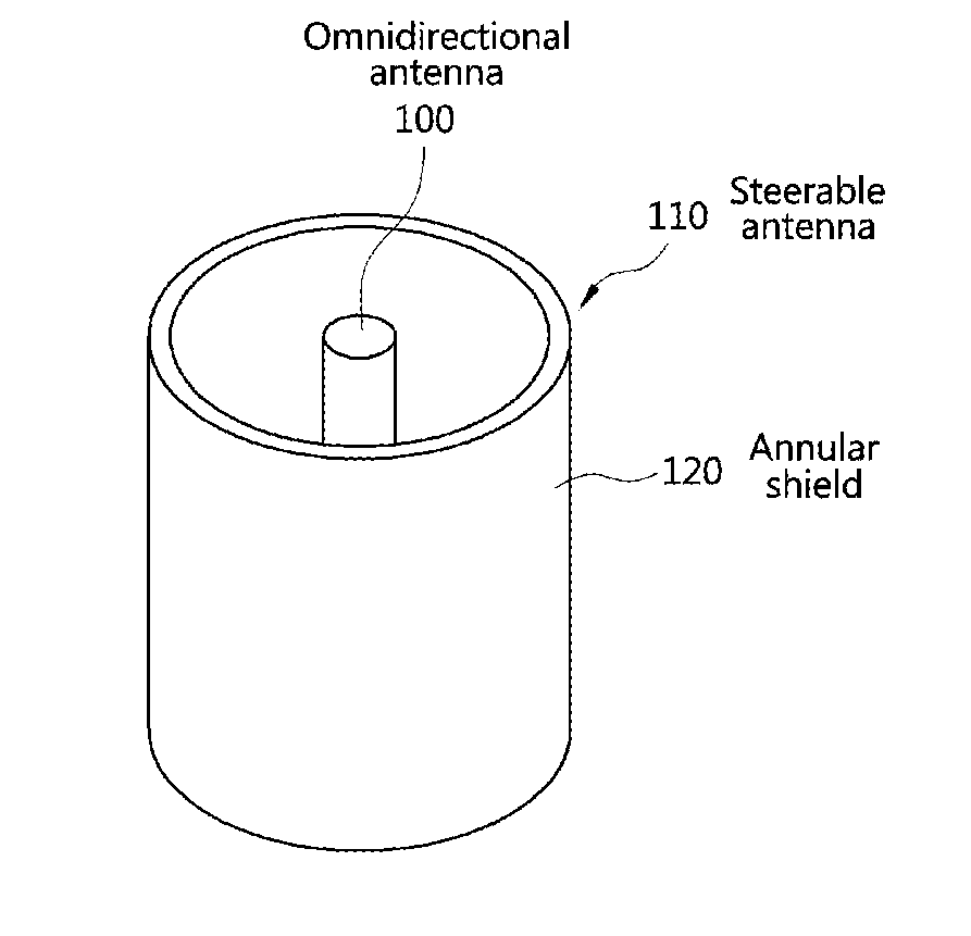
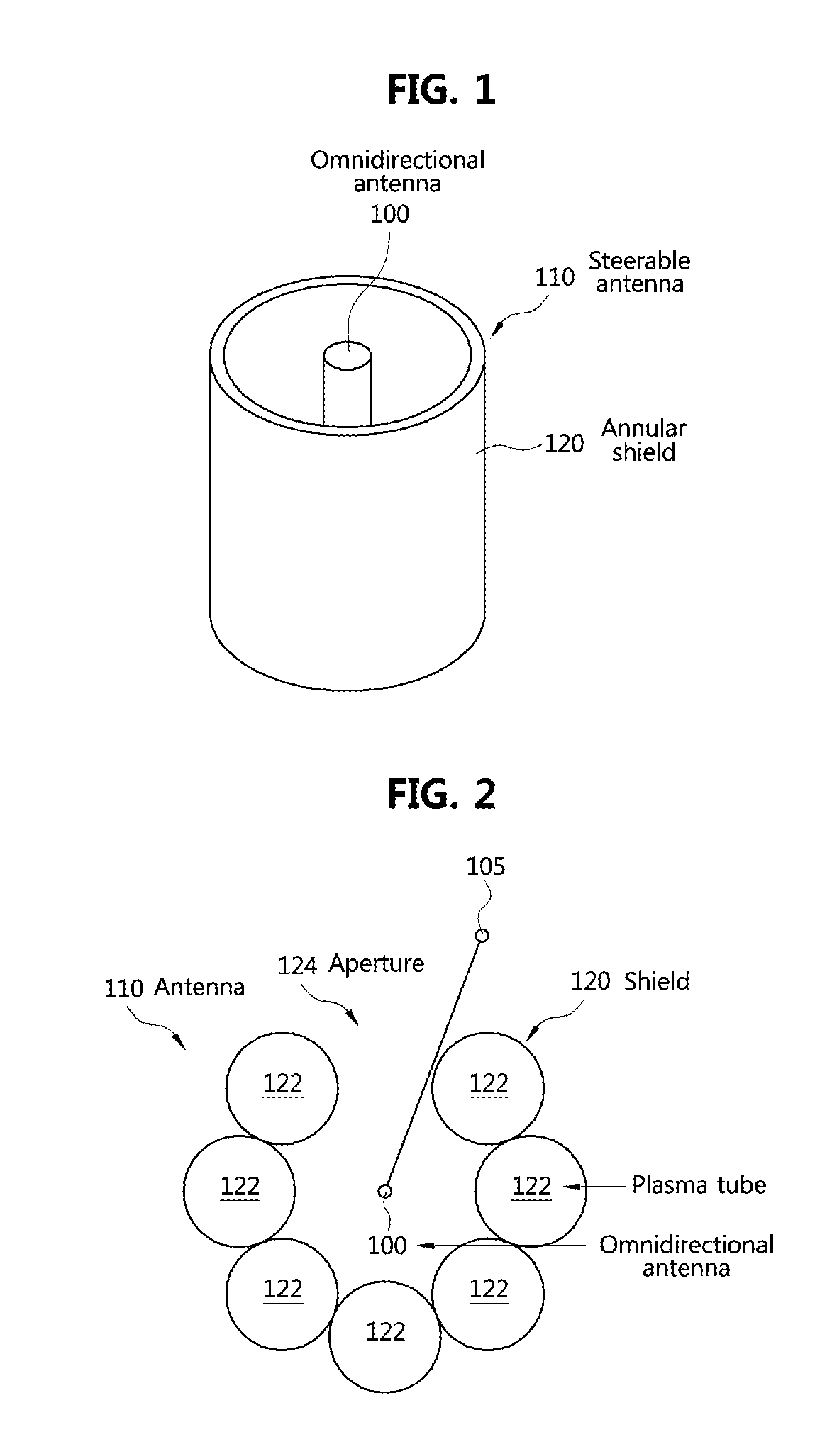
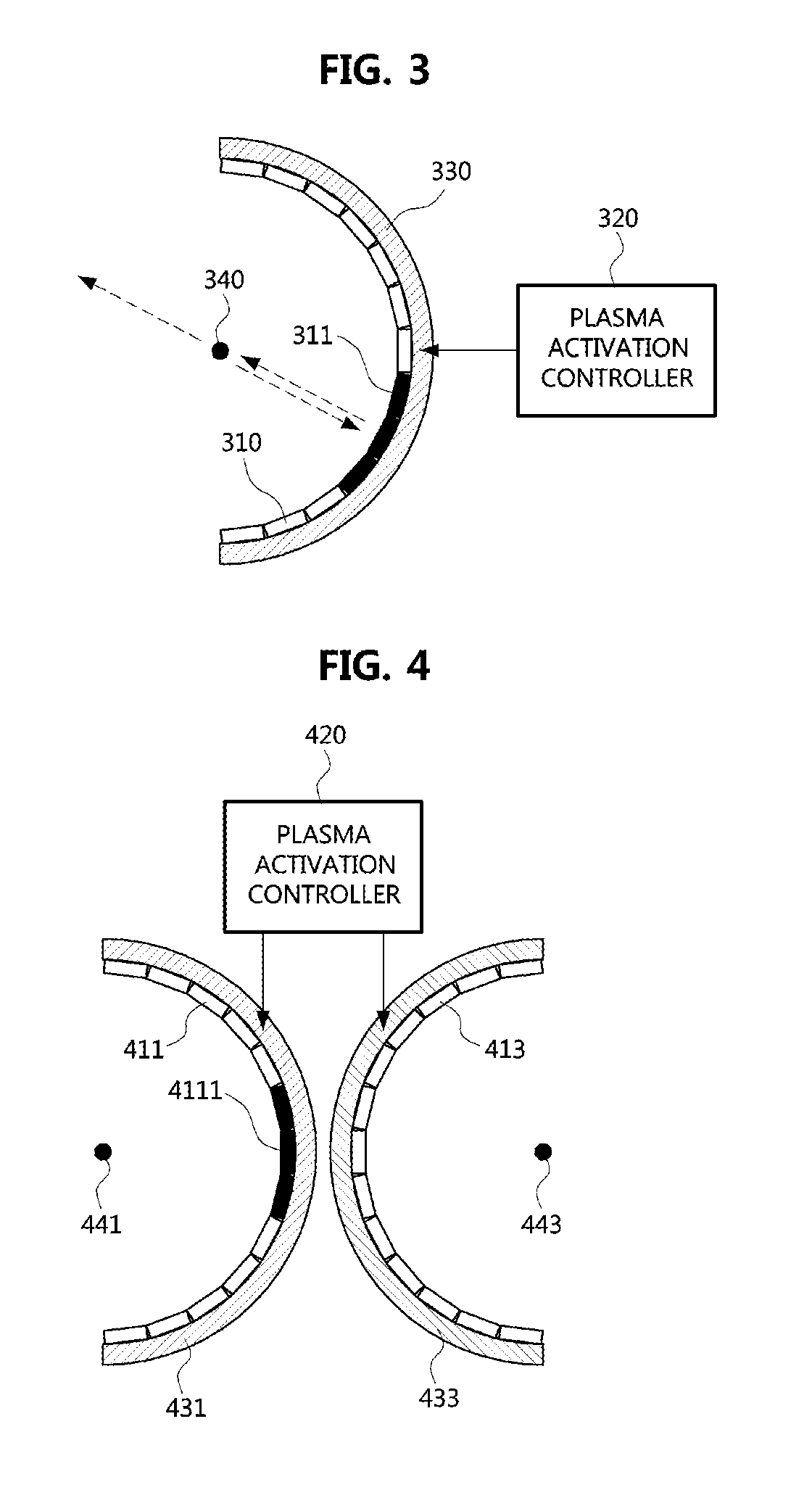
Solid-state plasma antenna
a plasma antenna and solid-state technology, applied in the direction of antennas, antenna details, electrical equipment, etc., can solve the problems of disturbing the propagation of radio waves
- Summary
- Abstract
- Description
- Claims
- Application Information
AI Technical Summary
Benefits of technology
Problems solved by technology
Method used
Image

Examples
Embodiment Construction
[0031]The present invention may be variously changed and may have various embodiments. Hereinafter, preferred embodiments of the present invention will be described in detail with reference to the accompanying drawings.
[0032]However, it should be understood that the present invention is not limited to these embodiments, and may include any and all modification, variations, equivalents, substitutions and the like within the spirit and scope thereof.
[0033]The terms ‘first,’‘second,’ and the like may be used to explain various other components, but these components are not limited to the terms. These terms are only used to distinguish one component from another. For example, a first component may be called a second component, and a second component may also be called a first component without departing from the scope of the present invention. The term ‘and / or’ means any one or a combination of a plurality of related and described items.
[0034]When it is mentioned that a certain componen...
PUM
 Abstract
Description
Claims
Application Information