Brushless DC motor

a brushless dc motor and motor body technology, applied in the direction of dynamo-electric machines, structural associations, supports/encloses/casings, etc., can solve the problems of reducing the elasticity of the engagement claw, and reducing the risk of damage to the engagement claw or the sensor board, so as to achieve the effect of limiting the damage to the engagement claw and fixing in place easily and reliably

Active Publication Date: 2015-07-30
TOKYO PARTS IND CO LTD
View PDF2 Cites 8 Cited by
  • Summary
  • Abstract
  • Description
  • Claims
  • Application Information

AI Technical Summary

Benefits of technology

[0019]According to one or more embodiments of the present invention, the positioning projections on the electrically insulating member are inserted into the positioning recesses on the sensor board and the sensor board is positioned in the circumferential direction, before the sensor board is fixed in place on the electrically insulating member by way of engaging the engagement parts on the sensor board with the engagement claws of the electrically insulating member. As a result, when the sensor board is engaged by elastically deforming the engagement claws, the position of the sensor board will not shift in the circumferential direction. Accordingly, it is not necessary to rotate the sensor board in the circumferential direction so as to adjust the position after the sensor board has been engaged with the engagement claws, which effectively limits damage to the engagement claws of the electrically insulating member and the sensor board.
[0020]Furthermore, because the engagement claws of the electrically insulating member and the positioning projections are provided independently at mutually differing positions in the circumferential direction, even if the positioning projections are formed so as to be radially thick, in order to reliably prevent the sensor board from turning, this will not be detrimental to the elasticity of the engagement claws, and thus the sensor board can be fixed in place easily and reliably.

Problems solved by technology

If such a position shift occurs, a large force will be applied to the long thin engagement claws of the electrically insulating member, which may result in damage to the engagement claws.
Thus, the positioning of the sensor board in the circumferential direction is troublesome, and there is a risk of damaging the engagement claws or the sensor board when the member is rotated.
Furthermore, in the brushless DC motor described in Japanese Patent Laid-Open Publication No. 2008-54390, because anti-turn projections are provided on the inner faces of the engagement claws that engage the sensor substrate, forming high anti-turn projections is detrimental to the elasticity of the engagement claws, and thus engagement with the sensor board is not easy.
Meanwhile, if low anti-turn projections are formed, while this is not detrimental to the elasticity of the engagement claw, the anti-turn function may not be sufficient.

Method used


Image

  • Brushless DC motor
  • Brushless DC motor
  • Brushless DC motor

Examples


first exemplary embodiment

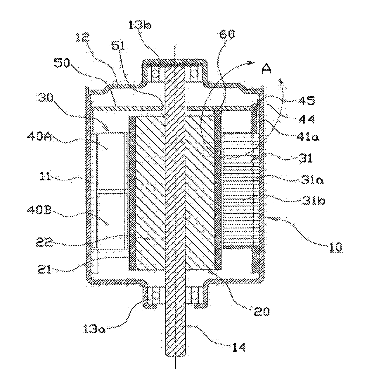
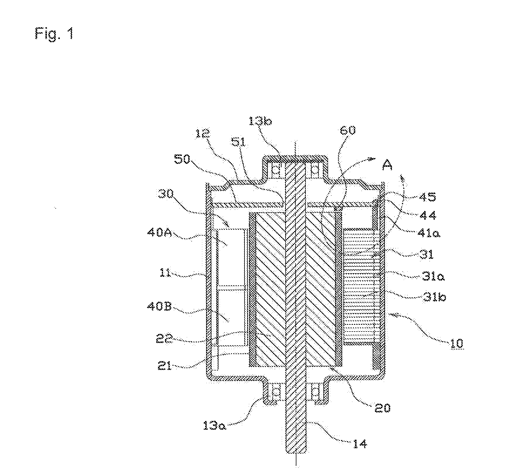
[0030]A first exemplary embodiment of the present invention will be described using FIG. 1 to FIG. 4. The brushless DC motor 10 of this example is an inner-rotor type motor, wherein a rotor 20 and a stator 30 are arranged in a substantially cylindrical space formed by a bottomed cylindrical case 11 and a bracket 12, which is mounted in an upper opening of the case 11.

[0031]The rotor 20 comprises a rotor core 22 and a cylindrical multi-pole magnet 21, which is fastened to the outer periphery of this rotor core 22. A rotary shaft 14 is united with the rotor 20 by way of press fitting into the center thereof. The rotary shaft 14 is rotatably supported by a bearing 13a that is fitted at the bottom center of the case 11, and a bearing 13b that is fitted at the center of the bracket 12.

[0032]The stator 30 comprises a stator core 31, in which a multiplicity of stacked planar cores having 9 teeth 31b which protrude inwardly at uniform intervals from an annular outer peripheral part 31a; an ...

second exemplary embodiment

[0055]A second exemplary embodiment of the present invention will be described using FIG. 5 and FIG. 6. In FIG. 5 and FIG. 6, the same reference numerals are used as were used for equivalent members and parts in FIG. 3 and FIG. 4, and redundant description has been omitted. Note that the basic configuration of the brushless DC motor in this example is the same as in FIG. 1.

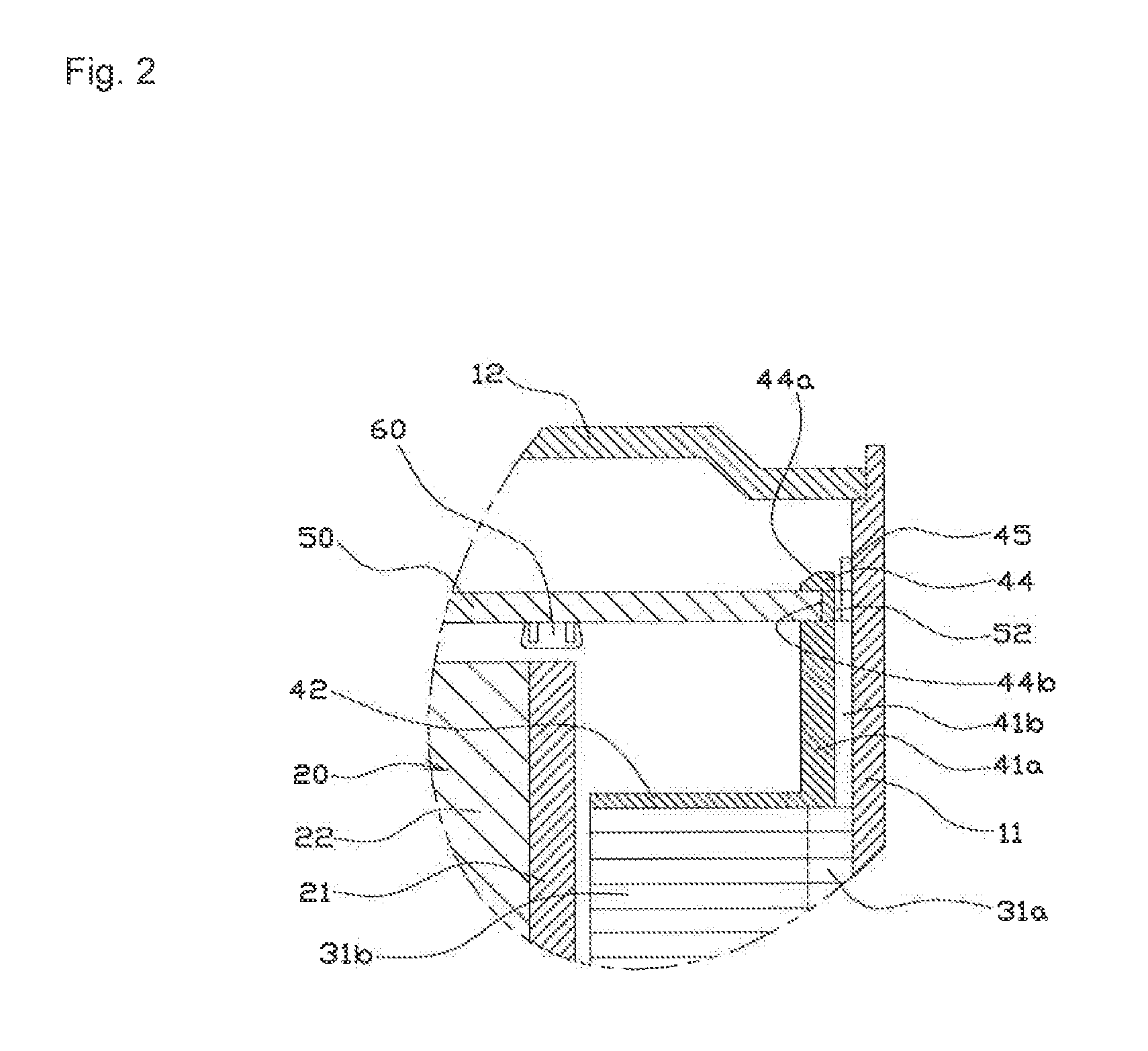
[0056]In this example as well, a plurality of engagement claws 44, which extend in the axial direction of the rotary shaft 14, and a plurality of positioning projections 45, at different positions in the circumferential direction than these engagement claws 44, which extend further than the engagement claws 44 in the axial direction of the rotary shaft 14, are provided on the top electrically insulating member 40A. Furthermore, the sensor board 50 is provided with engagement parts 52, which engage with the engagement claws 44, and positioning recesses 53 into which the positioning projections 45 are inserted.

[0057...

third exemplary embodiment

[0062]A third exemplary embodiment of the present invention will be described using FIG. 7 and FIG. 8. In FIG. 7 and FIG. 8, the same reference numerals are used as were used for equivalent members and parts in FIG. 3 and FIG. 4, and redundant description has been omitted. Note that the basic configuration of the brushless DC motor in this example is the same as in FIG. 1.

[0063]In this example as well, a plurality of engagement claws 44, which extend in the axial direction of the rotary shaft 14, and a plurality of positioning projections 45, at different positions in the circumferential direction than these engagement claws 44, which extend further than the engagement claws 44 in the axial direction of the rotary shaft 14, are provided on the top electrically insulating member 40A. Furthermore, the sensor board 50 is provided with engagement parts 52, which engage with the engagement claws 44, and positioning recesses 53 into which the positioning projections 45 are inserted.

[0064]...


PUM


Abstract

A electrically insulating member, which covers a stator core, has a plurality of engagement claws, which extend in the axial direction of a rotary shaft, and a plurality of positioning projections, at positions in the circumferential direction differing from those of the engagement claws, which extend further than the engagement claws. A sensor board, on which a plurality of magnetic sensors are fixed in place, has engagement parts, which engage with the engagement claws, and positioning recesses, into which the positioning projections are inserted.

Description

BACKGROUND OF THE INVENTION[0001]The present invention relates to a brushless DC motor, and in particular relates to technology for limiting variation in the capacity to detect the rotational position of the rotor.[0002]Brushless DC motors comprise a stator having drive coils on the teeth of a core, a rotor having a magnet, and a sensor board having magnetic sensors that detect the position of the magnetic poles in this rotor. The rotor core is rotated by generating a rotating magnetic field, by way of successively electrifying each of the drive coils on the stator in accordance with the positions of the magnetic poles in the rotor, which are detected by this magnetic sensor.[0003]With such a brushless DC motor, it is necessary to limit variation in the capacity to detect the rotational position of the rotor and, for this reason it is necessary to limit variation in the axial distance between the magnetic sensor and the magnet, while also limiting variation in the relative positions...

Claims


Application Information

Patent Timeline
Patent Type & Authority Applications(United States)
IPC IPC(8): H02K5/22H02K11/00
CPCH02K11/0021H02K5/22H02K11/215
Inventor NISHIDATE, MASAHIRO
Owner TOKYO PARTS IND CO LTD
Why Eureka
Try Eureka