Orthopaedic implant template and method of making

Inactive Publication Date: 2015-08-06
BIOMET MFG CORP
View PDF12 Cites 4 Cited by
  • Summary
  • Abstract
  • Description
  • Claims
  • Application Information

AI Technical Summary

Benefits of technology

The present invention offers a low-cost item that is easy to make and dispose of. It can be used as a single tool to save money and reduce waste.

Problems solved by technology

With the trend toward a total sterile environment for orthopaedics, the existing templates require re-sterilization and indefinite use, thereby increasing the total cost of the medical procedure.

Method used


Image

  • Orthopaedic implant template and method of making
  • Orthopaedic implant template and method of making
  • Orthopaedic implant template and method of making

Examples


Embodiment Construction

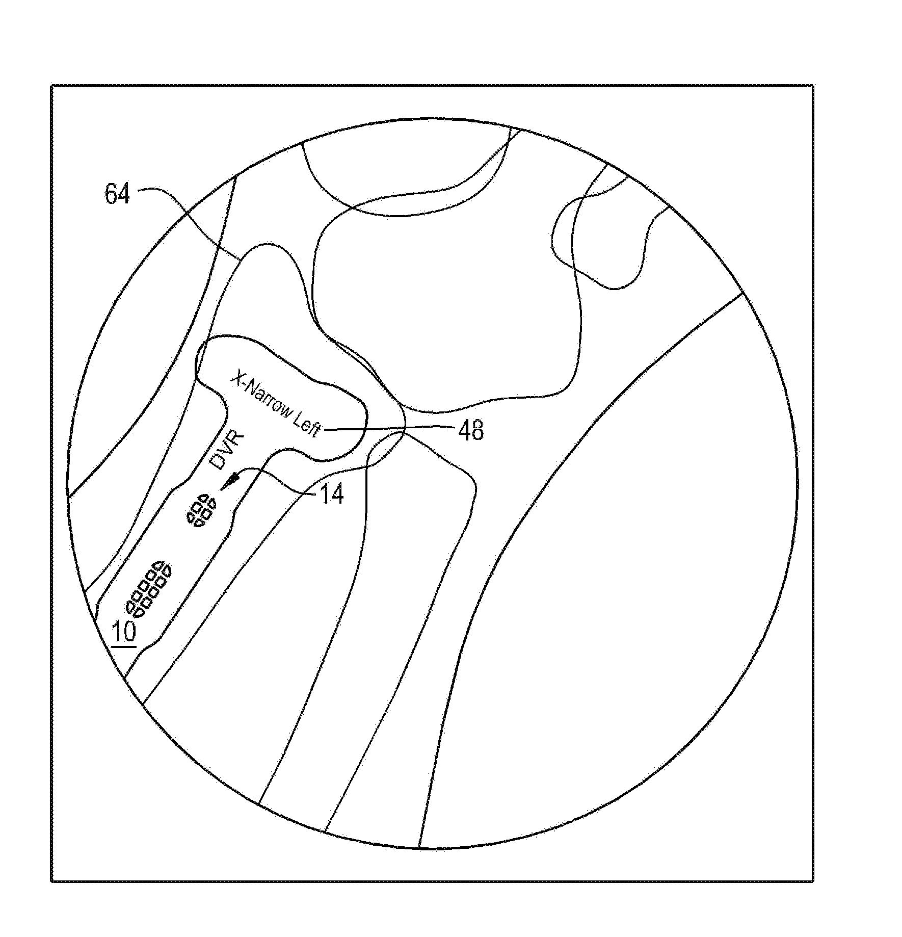
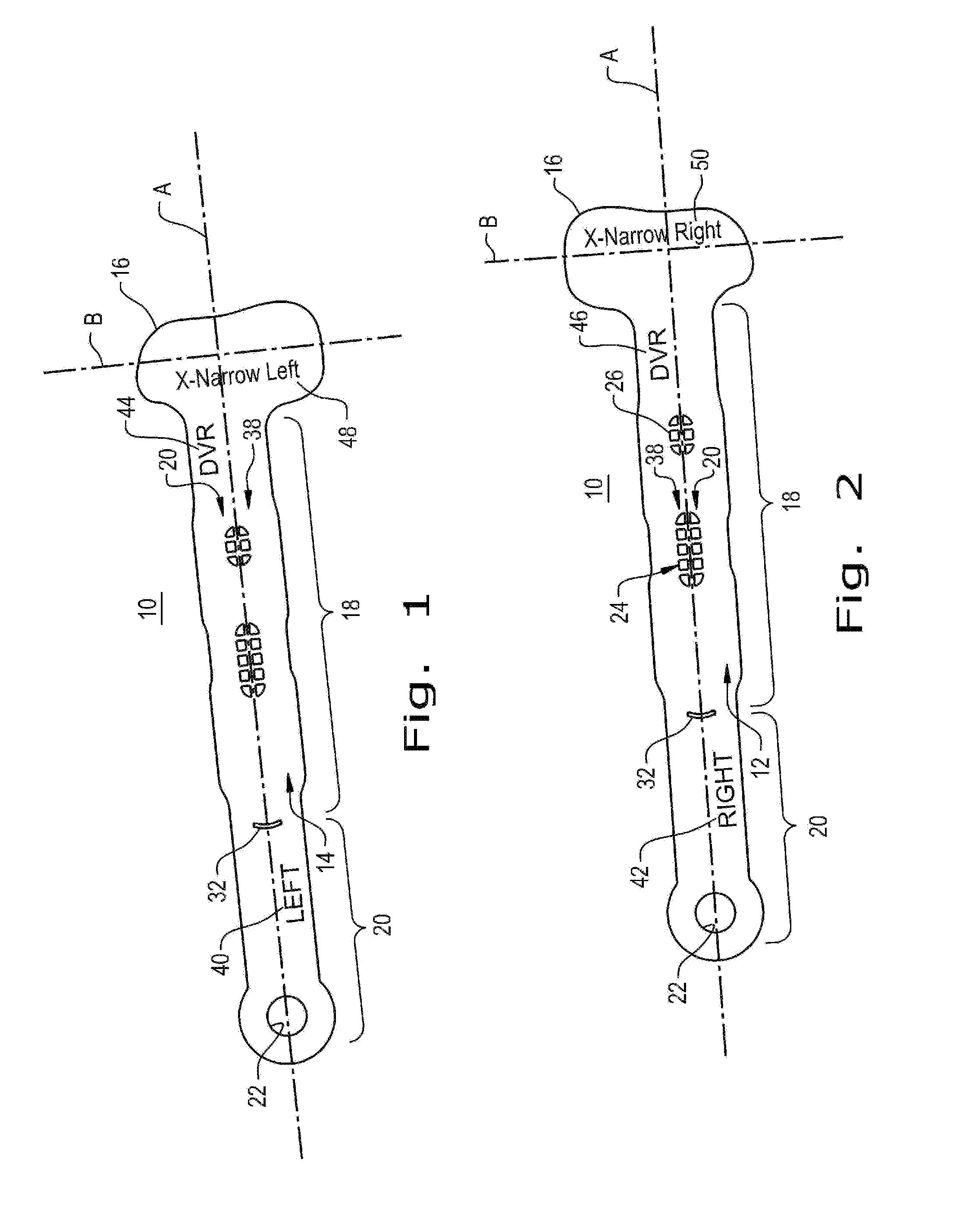
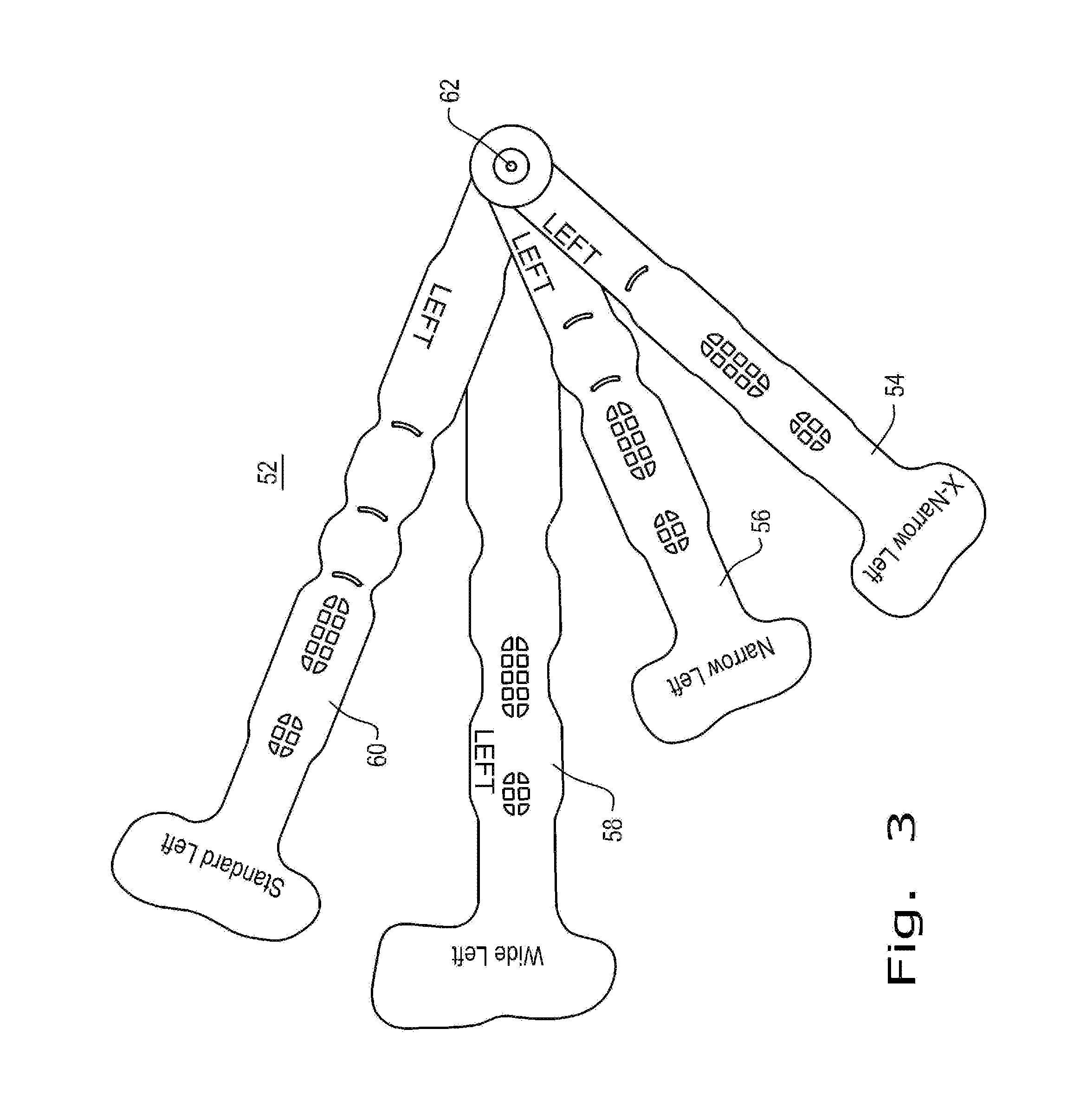
[0016]Referring specifically to FIGS. 1 and 2, there is shown a template 10 formed according to the present invention. The template 10 has a right face 12 and left face 14 shown in FIGS. 2 and 1 respectively. The template 10 has a proximal section 16 having a configuration that represents the outline of an implant to be used in orthopaedic surgery. The shape of proximal section 16 is simply illustrative of one of many shapes that may be employed for this purpose. A distal section 18 is integral with the proximal section 16 and represents the portion of an implant that is fastened to bone material. A base section 20 is integral with and extends from distal section 18 and terminates with a opening 22 to be used in connection with an array of templates 10, as described below.

[0017]The template 10 has a longitudinal axis A and an additional reference axis B extending tangentially with respect to axis A within the proximal section 16. A plurality of holes 24 and 26 are provided in the pr...


PUM

PropertyMeasurementUnit
Fractionaaaaaaaaaa
Thicknessaaaaaaaaaa
Lengthaaaaaaaaaa

Abstract

A template for orthopaedic bone implants formed from bio-compatible steel using photo chemical machining and etching. The template is processed on both faces to form right and left guides for implant fasteners and length indicators. Indicia are etched on opposite faces so that it does not overlie one another and presents sufficient contrast to be observed in an x-ray. The manufacturing cost is sufficiently low that the template may be provided in a single use form.

Description

BACKGROUND OF THE INVENTION[0001]1. Field of the Invention[0002]The present invention relates to orthopaedic devices, and, more specifically, to templates and methods of making same for orthopaedic implants.[0003]2. Description of the Related Art[0004]The field of orthopaedics has been moving towards sterile options regarding the equipment used during surgical procedures. This trend has as its objective, lower risk of infection, insured product integrity and potential improvement in efficiency of care.[0005]One aspect experiencing increased attention is in the area of a template or trial that is used for sizing orthopaedic implant devices used to repair a trauma or other problem with bone material. The templates are used to select the proper size implant during a surgical procedure to avoid contamination of a very expensive implant device, if it proves to be not the right size for a particular application. Currently, such templates are manufactured from machined, stainless steel or ...

Claims


Application Information

Patent Timeline
IPC IPC(8): A61B19/00C23F1/02
CPCA61B19/46A61B2019/461C23F1/02A61F2/4657A61B90/06A61B2090/061A61F2/3094A61F2/4261A61F2002/4658A61B17/8061A61B17/80A61B34/00
Inventor SIXTO, ROBERTSUAREZ, ANDREAKORTENBACH, JUERGEN
Owner BIOMET MFG CORP
Why Eureka
Try Eureka