Thermal management system for electric vehicle and its control method

a technology of electric vehicles and management systems, applied in the direction of battery/fuel cell control arrangements, electrochemical generators, transportation and packaging, etc., can solve the problems of difficult control of battery temperature within the desired temperature range, and achieve the effect of efficient storage of battery charging heat and more reliability

Active Publication Date: 2015-08-06
HIGHLY MARELLI JAPAN CORPORATION
View PDF4 Cites 77 Cited by
  • Summary
  • Abstract
  • Description
  • Claims
  • Application Information

AI Technical Summary

Benefits of technology

[0010]According to these aspects, it is possible to store charging heat generated from the battery at the time of charging the battery, by using heat mass of the refrigerant loop for the battery as a cooling system of the battery. When it is necessary to heat the battery, the refrigerant for the battery is heated by the heating device, and excess heat can be absorbed by the refrigerant loop for the air conditioner. Thus, it is possible to store the charging heat of the battery efficiently, and to control the temperature of the battery within the desired temperature range with more reliability.

Problems solved by technology

This results in a reduction of a following property of the refrigerant cycle, when the heating and the cooling of the battery are repeated at the time of charging the battery, which causes a difficulty in controlling the temperature of the battery within a desired temperature range.

Method used


Image

  • Thermal management system for electric vehicle and its control method
  • Thermal management system for electric vehicle and its control method
  • Thermal management system for electric vehicle and its control method

Examples


Embodiment Construction

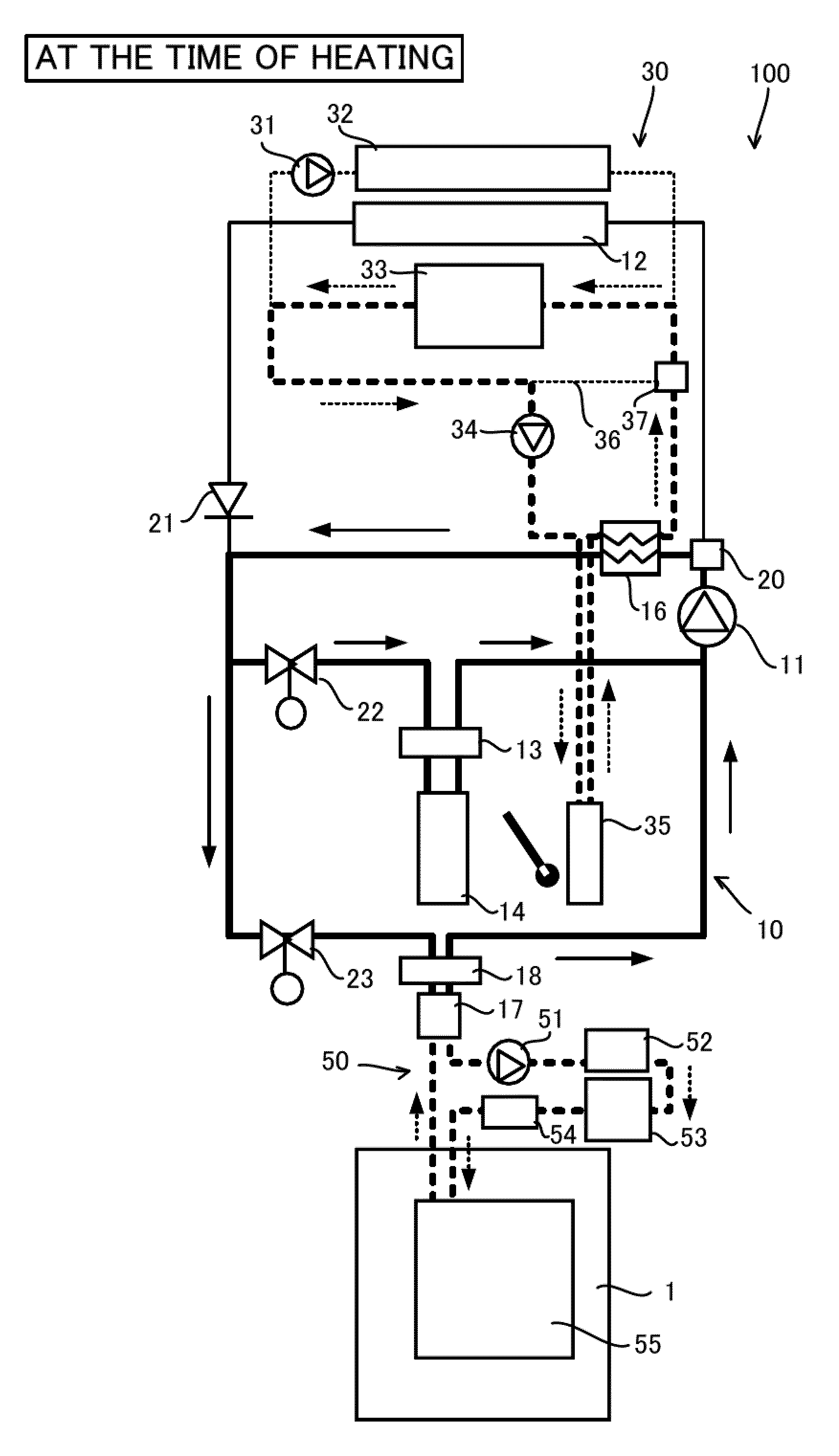
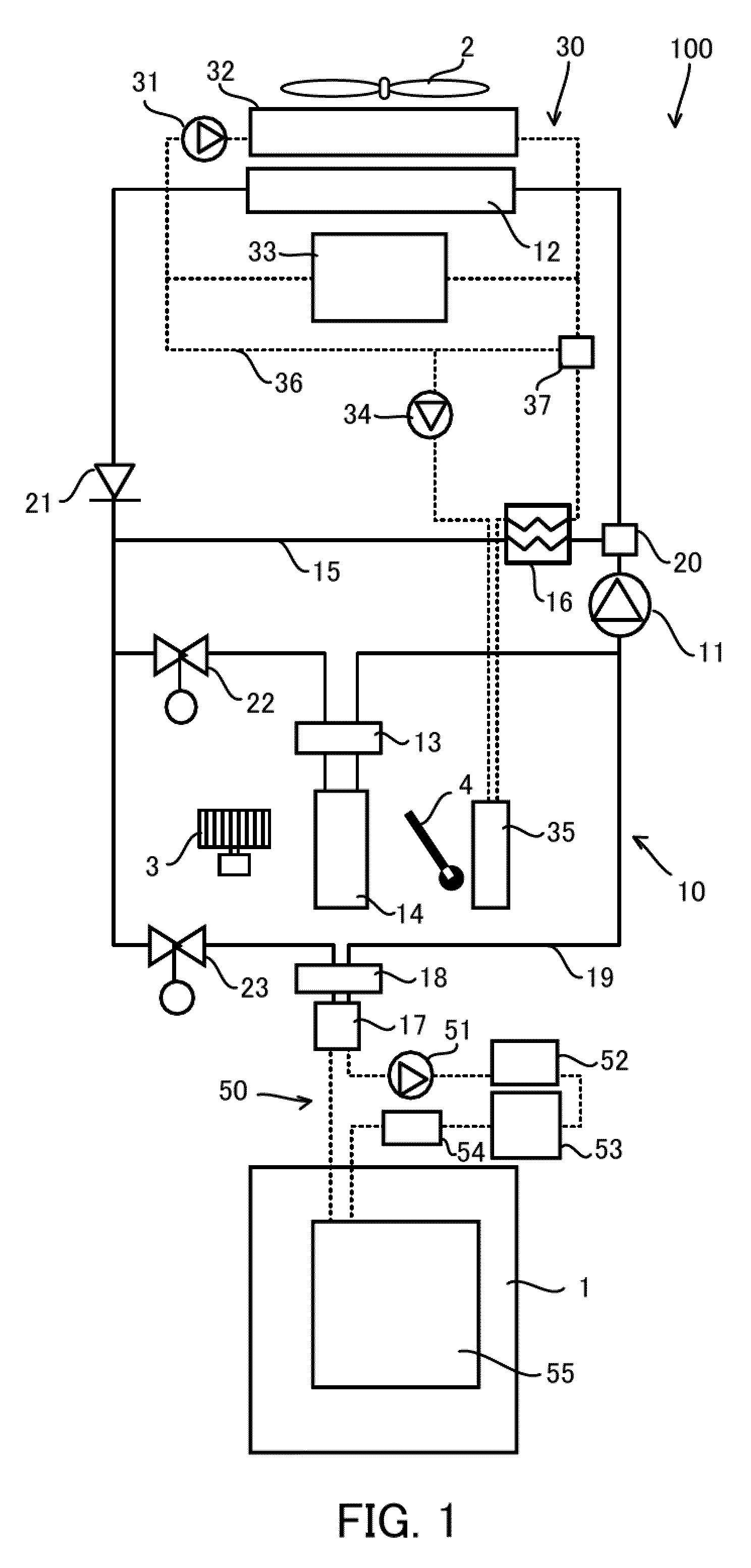
[0029]FIG. 1 illustrates the entire constitution of a thermal management system for an electric vehicle 100 according to the present invention.

[0030]The thermal management system for the electric vehicle 100 is provided with an air conditioner loop 10, a high water temperature loop 30, and a low water temperature loop 50.

[0031]An explanation will be given to the air conditioner loop 10.

[0032]The air conditioner loop 10 is a refrigerant circuit that forms a refrigeration cycle in which a refrigerant (such as HFC134a, for example) is circulated in the order of a compressor 11, a condenser 12, an expansion valve 13, and an evaporator 14.

[0033]The compressor 11, driven by an electric motor, compresses refrigerant gas and discharges the compressed refrigerant gas having high temperature and high pressure.

[0034]The condenser 12 exchanges heat between the compressed refrigerant gas and outside air and radiates the heat of the compressed refrigerant gas to the outside air, so that the compr...


PUM


Abstract

A thermal management system for an electric vehicle that is used in the electric vehicle driven by an electric motor includes a refrigerant loop for an air conditioner, a refrigerant loop for a battery that allows a refrigerant for the battery to circulate among the battery, an evaporating unit and a heating device, and thermal management controlling means that, during charging of the battery, heats the refrigerant for the battery by using the heating device when temperature of the refrigerant for the battery is lower than target temperature of the refrigerant for the battery, and that allows the refrigerant for the air conditioner to circulate and to absorb heat from the refrigerant for the battery, in the evaporating unit, when the temperature of the refrigerant for the battery is higher than the target temperature of the refrigerant for the battery.

Description

TECHNICAL FIELD[0001]The present invention relates to a thermal management system for an electric vehicle that is mounted on the electric vehicle and its control method.BACKGROUND ART[0002]An electric vehicle that travels by a driving force of an electric motor cannot use waste heat of an engine at the time of heating, since the engine is not mounted thereon. Further, the amount of heat at the time of heating is not enough even in an electric vehicle on which the engine is mounted, such as a hybrid vehicle, since it does not operate the engine at all times. For this reason, an air conditioning device that is formed by a refrigerant cycle having an electric compressor is used at the time of heating, so as to increase temperature inside a cabin.[0003]However, power accumulated in a battery is consumed by the amount used for operating the air conditioning device, which results in a reduction in cruising distance of the vehicle.[0004]JP2011-68348A discloses an air conditioning system pr...

Claims


Application Information

Patent Timeline
Patent Type & Authority Applications(United States)
IPC IPC(8): B60H1/00B60H1/22
CPCB60L1/003B60H1/2215B60L11/1862B60L11/1874B60L2240/36B60L2240/545Y02T10/7044Y02T10/7005Y02T10/705B60H1/00278B60H1/3208B60H2001/00307B60H2001/3261B60H2001/3263B60H1/22B60H1/32H01M10/60H01M10/663B60L1/02B60L58/13B60L58/26Y02E60/10Y02T10/70
Inventor HATAKEYAMA, JUNISHIKAWA, TAKAYUKIKOSHIKAWA, MASASHIOGIHARA, SATOSHISHIMONOSONO, HITOSHI
Owner HIGHLY MARELLI JAPAN CORPORATION
Why Eureka
Try Eureka