Light source module, backlight assembly including the same, and display device including the light source module

a technology of backlight assembly and light source module, which is applied in the direction of lighting and heating apparatus, semiconductor devices for light sources, instruments, etc., can solve the problems of inability to use in a place without light source, deterioration of the display quality of the display device, and non-uniform luminance, so as to improve the light quality of the backlight assembly including the led chip, improve the uniformity of luminance, and improve color purity

Active Publication Date: 2015-08-06
SAMSUNG DISPLAY CO LTD
View PDF9 Cites 36 Cited by
  • Summary
  • Abstract
  • Description
  • Claims
  • Application Information

AI Technical Summary

Benefits of technology

[0008]Accordingly, exemplary embodiments of the invention provide a light source module with improved luminance uniformity.
[0009]Another exemplary embodiment of the invention provides a backlight assembly with improved light quality.
[0010]Another exemplary embodiment of the invention provides a display device with improved display quality.
[0031]According to the exemplary embodiments of the invention, at least the following effects can be achieved.
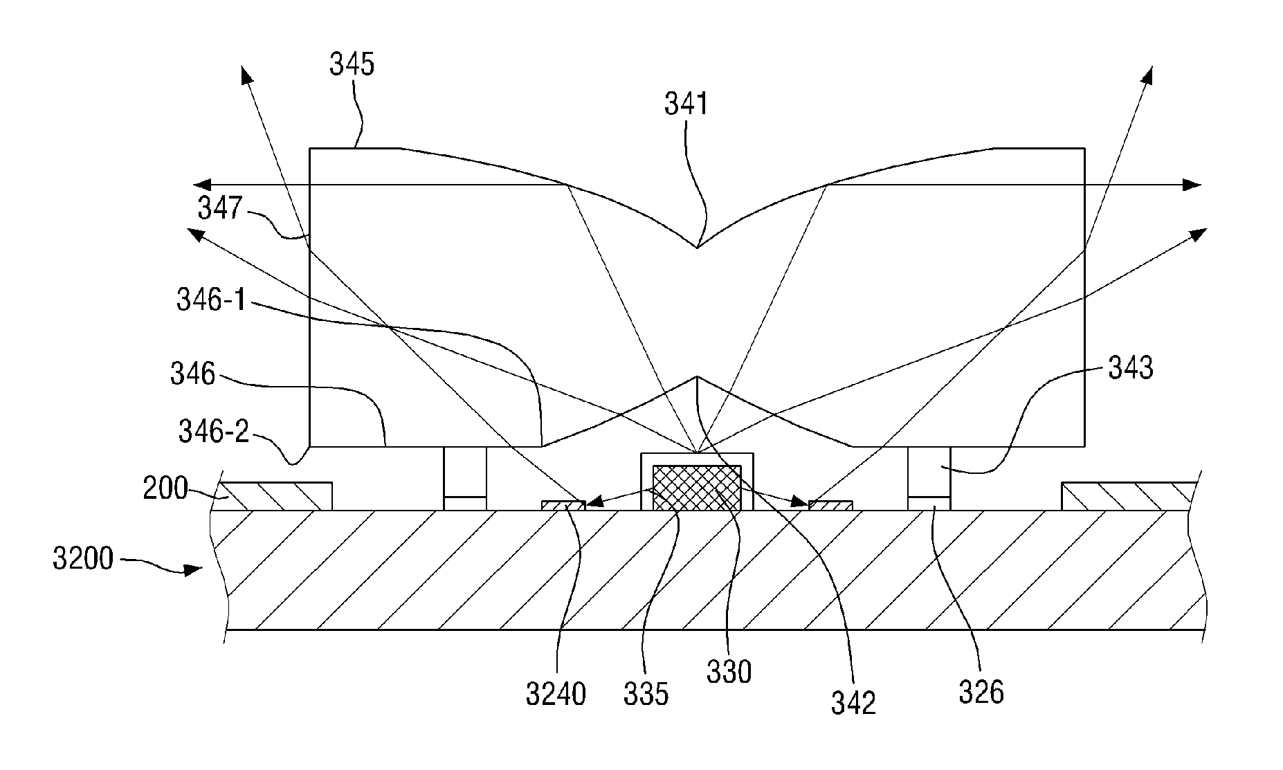
[0032]That is, the amount and / or the color of the light that is refracted to the upper portion of the LED chip can be controlled by the reflection adjustment pattern disposed on the PCB. Accordingly, the luminance uniformity can be improved and the color purity can be improved.
[0033]Further, the light quality of the backlight assembly including the LED chip can be improved, and thus the display quality of the display device can be improved.

Problems solved by technology

Unlike a cathode ray tube (“CRT”) or a plasma display panel (“PDP”), the LCD is not self-luminous, and thus is unable to be used in a place where no light source is provided.
However, when light that is emitted from a side portion or a lower portion of the LED light source is reflected by a printed circuit board (“PCB”) and is incident to the optical lens, the incident light is refracted in an upper direction, and a large amount of light may be concentrated just above the LED light source to cause luminance non-uniformity to occur.
When the luminance of the light that is emitted from the light source module becomes non-uniform, the light quality of the backlight that includes the light source module and the display quality of the display device may be deteriorated.

Method used


Image

  • Light source module, backlight assembly including the same, and display device including the light source module
  • Light source module, backlight assembly including the same, and display device including the light source module
  • Light source module, backlight assembly including the same, and display device including the light source module

Examples


Embodiment Construction

[0054]Advantages and features of the invention and methods of accomplishing the same may be understood more readily by reference to the following detailed description of preferred embodiments and the accompanying drawings. The invention may, however, be embodied in many different forms and should not be construed as being limited to the embodiments set forth herein. Rather, these embodiments are provided so that this invention will be thorough and complete and will fully convey the concept of the invention to those skilled in the art, and the invention will only be defined by the appended claims.

[0055]It will also be understood that when a layer is referred to as being “on” another layer or substrate, it can be directly on the other layer or substrate, or intervening layers may also be present. The same reference numbers indicate the same components throughout the specification.

[0056]It will be understood that, although the terms first, second, third etc. may be used herein to descr...


PUM

PropertyMeasurementUnit
widthaaaaaaaaaa
reflectionaaaaaaaaaa
widthaaaaaaaaaa

Abstract

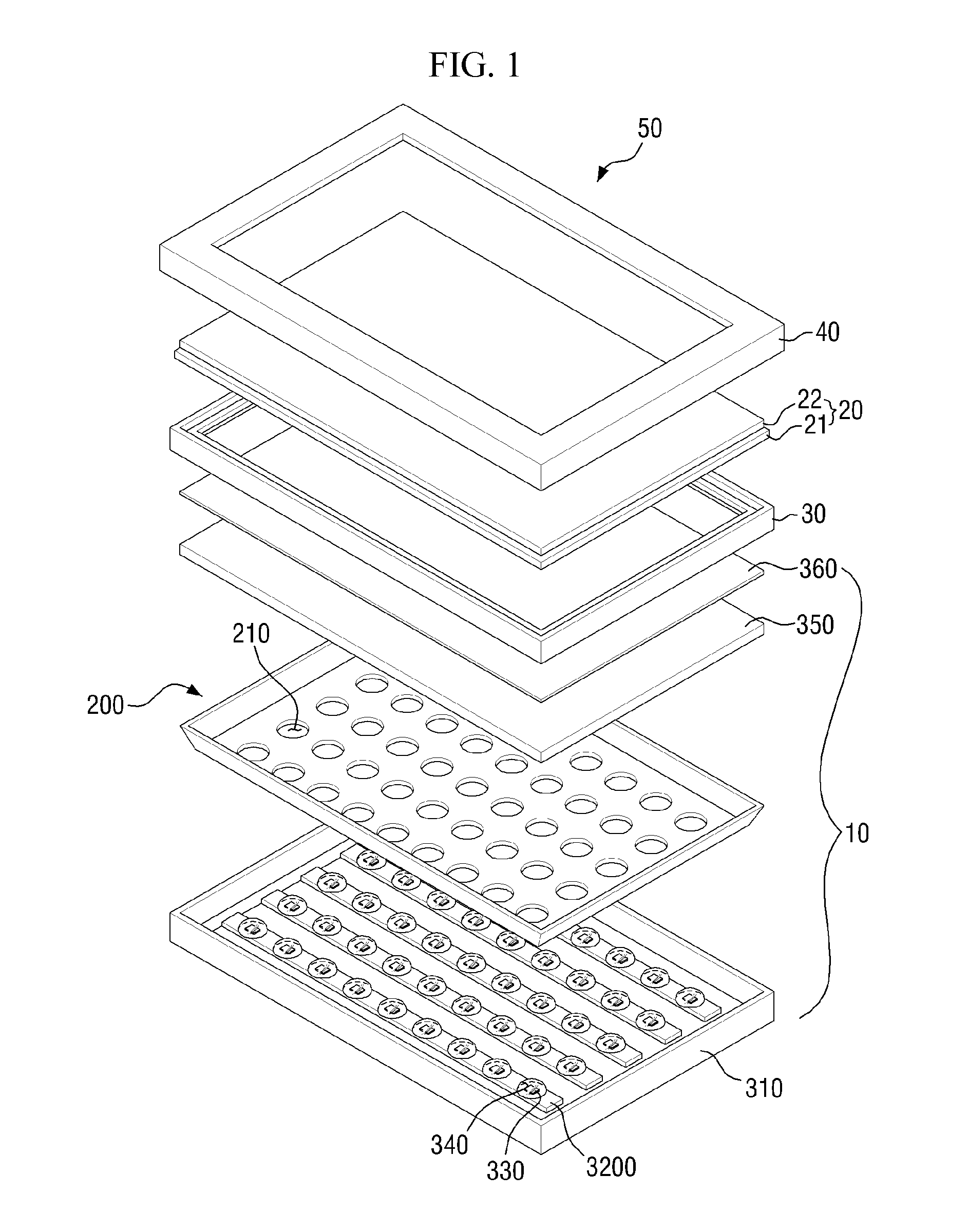
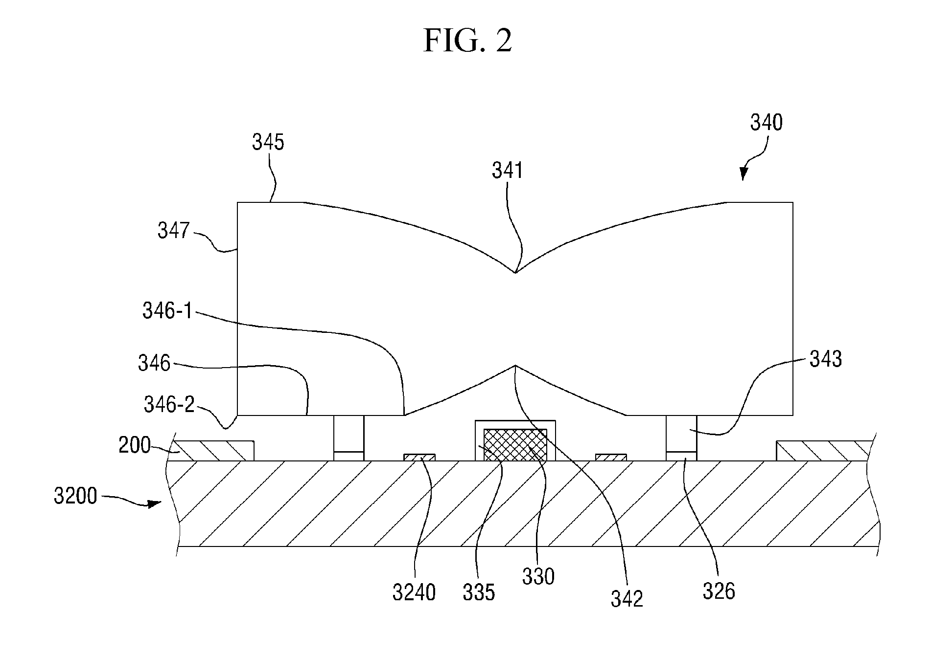
A light source module includes a printed circuit board including a wiring layer, an insulating coating layer disposed on the wiring layer, and a reflection adjustment pattern disposed on the insulating coating layer and having reflection characteristics which are different from reflection characteristics of the insulating coating layer, a light emitting chip mounted on the printed circuit board, and an optical lens arranged on an upper portion of the light emitting chip and fixed to the printed circuit board.

Description

[0001]This application claims priority to Korean Patent Application No. 10-2014-0013175, filed on Feb. 5, 2014, and all the benefits accruing therefrom under 35 U.S.C. §119, the disclosure of which is incorporated herein in its entirety by reference.BACKGROUND[0002]1. Field of the Invention[0003]The invention relates to a light source module, a backlight assembly including the same, and a display device including the light source module.[0004]2. Description of the Prior Art[0005]A liquid crystal display (“LCD”) is a display device, in which liquid crystals are injected between two glass substrates, and the molecular orientation of the liquid crystals for each pixel is changed through application of a power to upper and lower glass substrate electrodes to display an image. Unlike a cathode ray tube (“CRT”) or a plasma display panel (“PDP”), the LCD is not self-luminous, and thus is unable to be used in a place where no light source is provided. In order to supplement such drawbacks, ...

Claims


Application Information

Patent Timeline
Patent Type & Authority Applications(United States)
IPC IPC(8): G02F1/1335F21V7/00F21V7/04F21V5/04F21V13/04F21V23/00
CPCF21V5/046G02F1/133611G02F1/133606G02F1/133605G02F1/133603F21Y2101/02F21V23/004F21V13/04F21V7/04F21V7/0066G02F2001/133607H05K1/0274H05K2201/10106H05K2201/10121H05K2201/2054F21Y2115/10G02B19/0028G02B19/0061G02B19/0071G02F1/133607
Inventor SONG, SI JOONKIM, HYUK HWANKIM, HYUN JEONGNAM, SEOK HYUNLEE, YOUNG KEUN
Owner SAMSUNG DISPLAY CO LTD
Why Eureka
Try Eureka