Trabecular bone analyzer

a trabecular bone and analyzer technology, applied in the field of trabecular bone analyzers, can solve the problems of inability to accurately quantify trabecular bone, inferior resolution of acquired tomographic images to fluoroscopic images, etc., to achieve accurate results, accurate quantification of trabecular bone, and high resolution

Active Publication Date: 2015-08-06
SHIMADZU CORP
View PDF16 Cites 7 Cited by
  • Summary
  • Abstract
  • Description
  • Claims
  • Application Information

AI Technical Summary

Benefits of technology

[0030]According to a conventional method, trabecular bone analysis is performed using a fluoroscopic image acquired by plain radiography. Such an analysis cannot always acquire an accurate result. This is because overlapping trabeculae unclearly appear in the fluoroscopic image. Further, it cannot be said that analysis using a CT device achieves a high resolution. On t

Problems solved by technology

However, such conventional methods have the following problem.
That is, the conventional trabecular bone analyzing methods have a problem that trabecular bone cannot be accurately quantified.
Even when trabecular bone analysis is performed based on such an image, trabecular bone cannot be accurately quantified.
On the other hand, in the case in which a tomographic image is taken by a CT device by rotating a radiation source and a detector once around a subject, the acquired tomographic image is inferior in resolution to a fluoroscopic image acquired by plain radiography, and in addition, a wide region of the subject is exposed to radiation.
Therefore, even when trabecular bone analysis is performed usin

Method used


Image

  • Trabecular bone analyzer
  • Trabecular bone analyzer
  • Trabecular bone analyzer

Examples


example 1

[0042]Hereinbelow, examples of a trabecular bone analyzer according to embodiments of the present invention will be described with reference to the accompanying drawings. It is to be noted that X-rays in the embodiments correspond to one example of radiation in the present invention. It is to be noted that FPD is an abbreviation for flat panel detector (such as a flat panel X-ray detector).

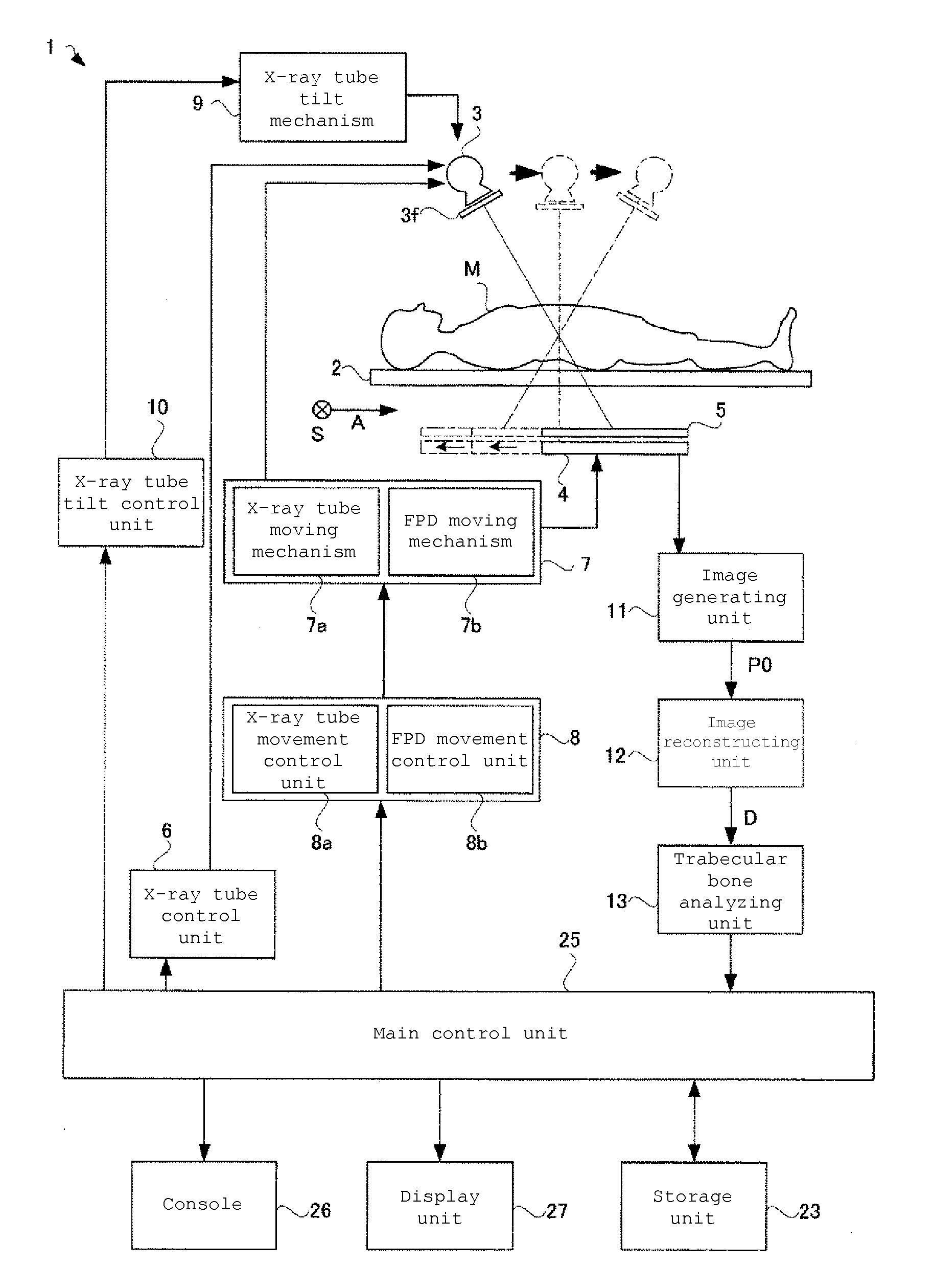
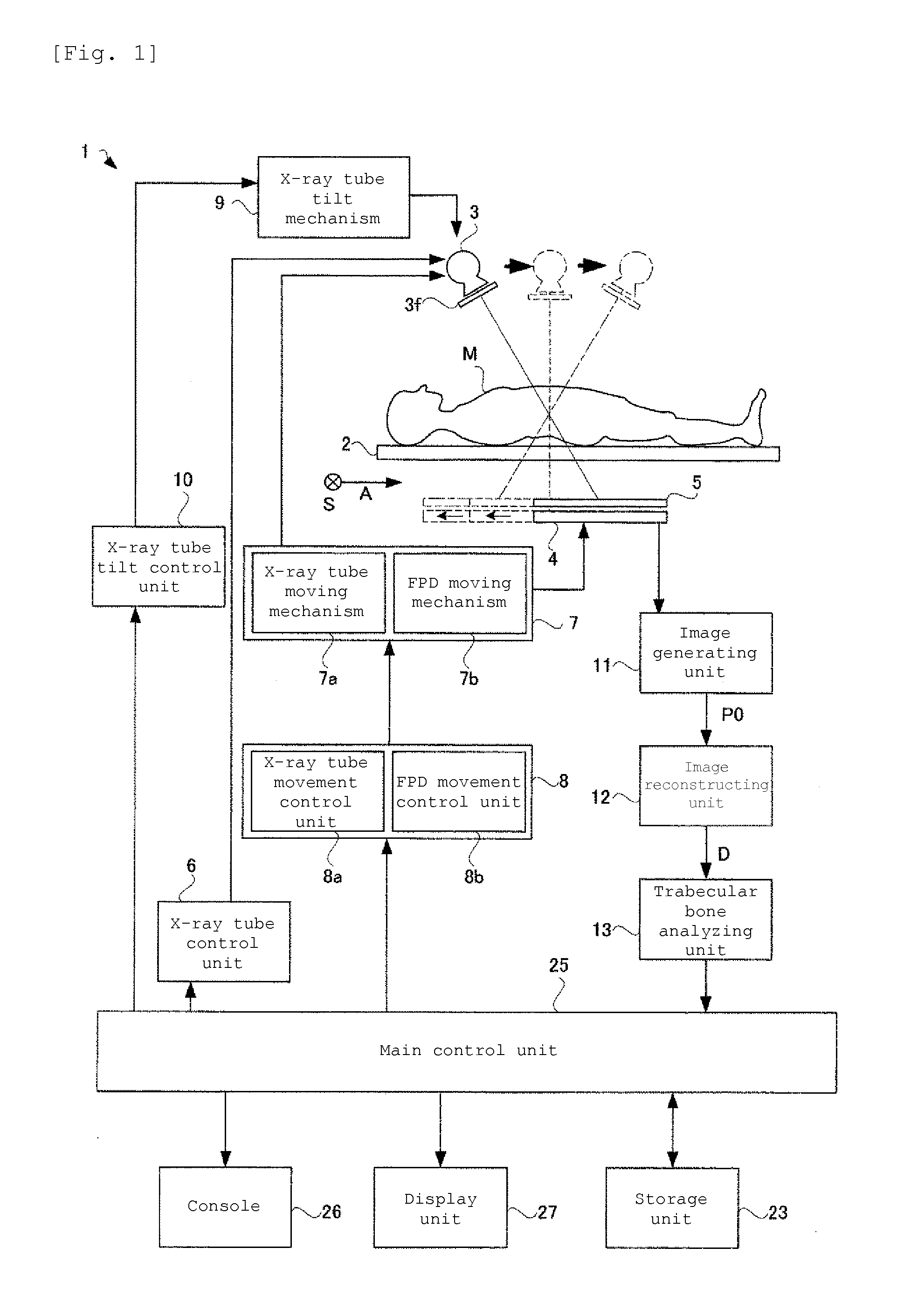
[0043]FIG. 1 is a functional block diagram illustrating the configuration of a trabecular bone analyzer according to Example 1. As shown in FIG. 1, the trabecular bone analyzer 1 according to Example 1 includes: a top board 2 on which a subject M as a target for X-ray tomography is to be placed; an X-ray tube 3 provided above the top board 2 (on one surface side of the top board 2) to irradiate the subject M with a cone-shaped X-ray beam; an FPD 4 provided blow the top board 2 (on the other surface side of the top board) to detect an X-ray fluoroscopic image of the subject M; a synchronous moving ...

example 2

[0081]Hereinbelow, a trabecular bone analyzer according to Example 2 will be described. As shown in FIG. 7, the trabecular bone analyzer according to Example 2 is configured so that a tomographic image can be taken by moving an X-ray tube 3 and an FPD 4 in the direction of a body axis A of a subject M with their positional relationship being maintained. Asynchronous moving mechanism 7 moves the X-ray tube 3 and the FPD 4 synchronously so that the X-ray tube 3 moves toward one end of a top board 2 in the longitudinal direction of the top board 2 and the FPD 4 moves toward one end of the top board 2 in the longitudinal direction of the top board 2.

[0082]The configuration of the X-ray radiographic device according to Example 2 is the same as that shown in the functional block diagram of FIG. 1. The configuration of Example 2 is different from that of Example 1 shown in FIG. 1 in that the FPD 4 moves while following the X-ray tube 3 (see FIG. 7) and the X-ray tube 3 does not tilt. There...


PUM


Abstract

Disclosed herein is a trabecular bone analyzer that can quantitatively determine the state of trabecular bone accurately. The trabecular bone analyzer of may perform trabecular bone analysis on a tomographic image D. In the tomographic image D, trabeculae forming a network may appear without overlapping. Therefore, such trabecular bone analysis may more accurately quantify trabecular bone.

Description

BACKGROUND OF THE INVENTION[0001]1. Field of the Invention[0002]The present invention relates to a trabecular bone analyzer for analyzing the trabecular bone of a subject. A trabecular bone analyzer may aquire and analyze a radiation fluoroscopic image of a subject to perform trabecular bone analysis.[0003]2. Description of the Related Art[0004]A trabecula is often a long and thin structure forming a spongy substance inside bones. The health or disease status of a subject M can be checked by determining whether such trabeculae are sufficiently present in a bone. Further, the bone strength of the subject M can be determined by analyzing the trabecular bone of the subject M.[0005]A conventional trabecular bone analyzing method will be described. As shown in FIG. 11, a conventional trabecular bone analyzer 50 includes a top board 52 on which a subject M is to be placed, a radiation source 53 provided above the top board 52, and a detector 54 provided below the top board 52. Trabecular ...

Claims


Application Information

Patent Timeline
IPC IPC(8): G06T7/00A61B6/03A61B6/00
CPCG06T7/0012A61B6/505G06T2207/30008A61B6/4476G06T2207/10081A61B6/032A61B6/025A61B6/4233G06T7/42G06T11/003G06T2207/10144G06T2207/20104
Inventor YAMAMOTO, JUNYA
Owner SHIMADZU CORP
Why Eureka
Try Eureka