Control method for achieving power transfer between stacked rechargeable battery cells and power transfer circuit thereof

a technology of stacked rechargeable battery cells and control methods, which is applied in the direction of battery circuits, transportation and packaging, safety/protection battery circuits, etc., can solve the problems of consuming extra power, defective heat generation circuits of rechargeable battery cells, etc., and achieves the effect of less power consumption, no unnecessary power consumption, and more power

Inactive Publication Date: 2015-08-06
HYCON TECH
View PDF3 Cites 9 Cited by
  • Summary
  • Abstract
  • Description
  • Claims
  • Application Information

AI Technical Summary

Benefits of technology

[0019]The control method and power transfer circuit according the present invention can utilize an inductor to buffer power from the rechargeable battery cell which has more power and compensate the other rechargeable battery cell which has less power. Balance between rechargeable battery cells can be achieved and no unnecessary power is consumed.

Problems solved by technology

The known balance circuit for rechargeable battery cells has defects of generating heat and extra consuming power.

Method used


Image

  • Control method for achieving power transfer between stacked rechargeable battery cells and power transfer circuit thereof
  • Control method for achieving power transfer between stacked rechargeable battery cells and power transfer circuit thereof
  • Control method for achieving power transfer between stacked rechargeable battery cells and power transfer circuit thereof

Examples


Embodiment Construction

[0027]The present invention will now be described more specifically with reference to the following embodiment.

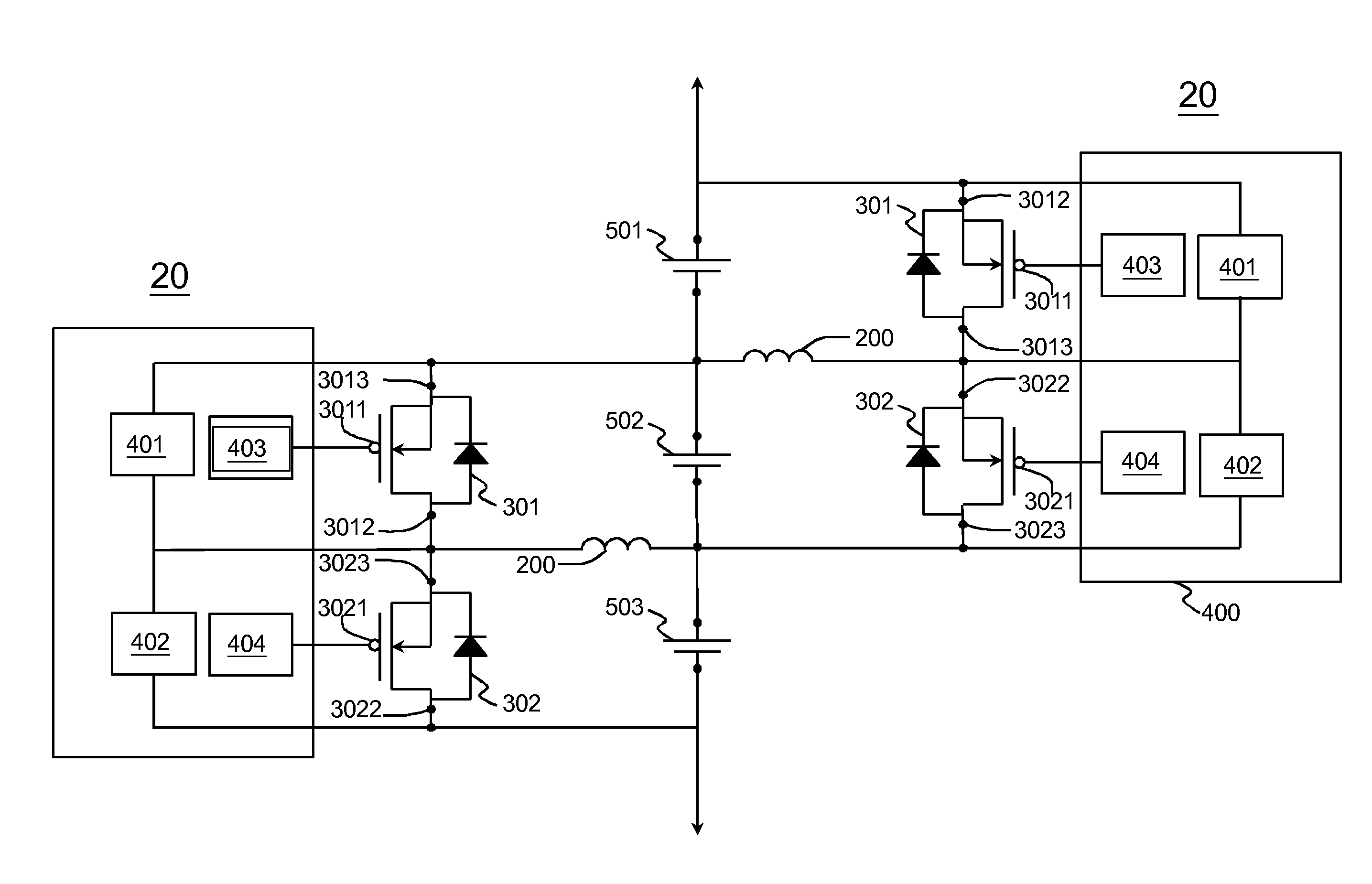
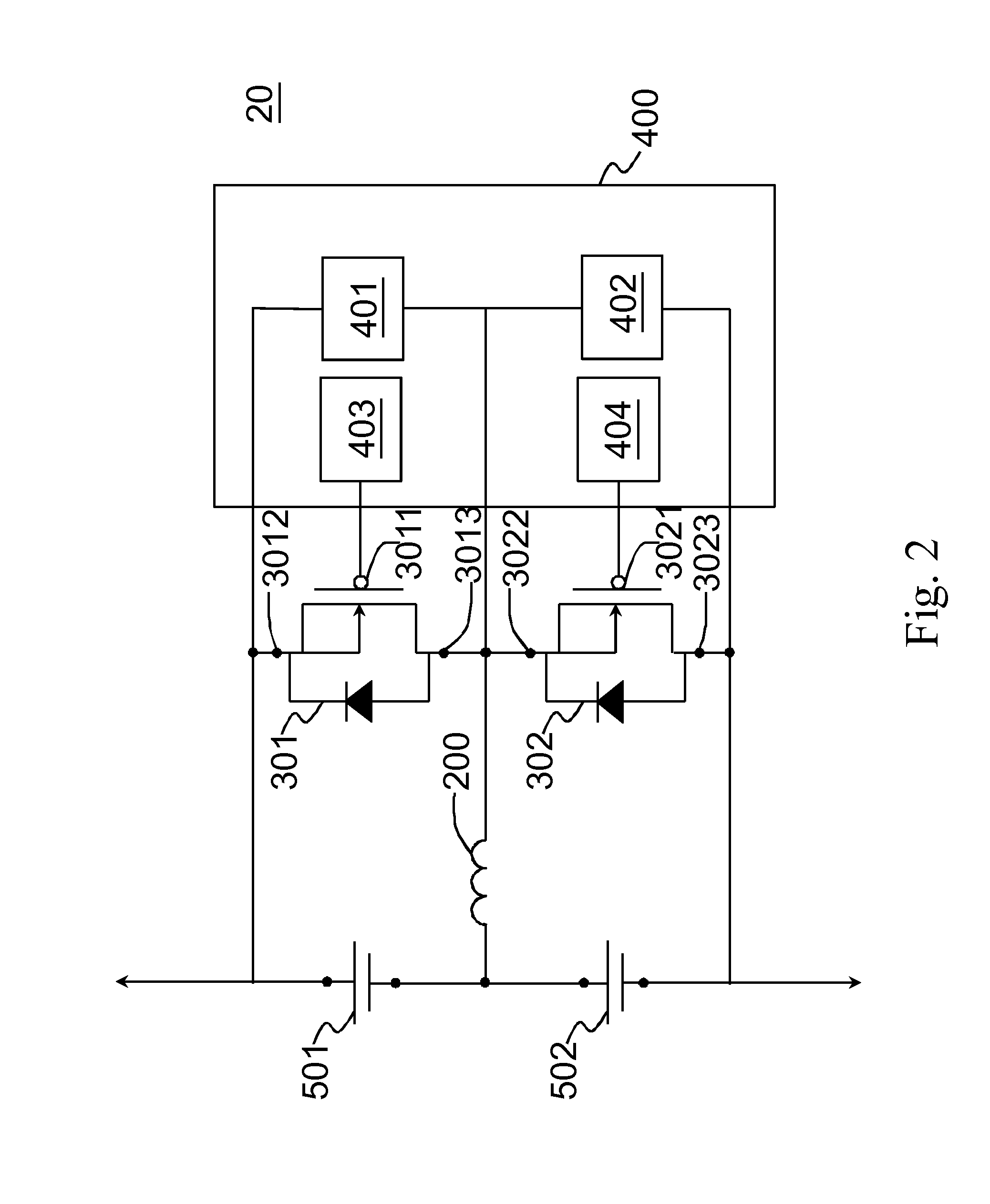
[0028]Please refer to FIG. 2 to FIG. 7. FIG. 2 is a block diagram of a power transfer circuit according to the present invention. FIG. 3 illustrates an inductor in the power transfer circuit stores power. FIG. 4 illustrates the inductor in the power transfer circuit releases stored power. FIG. 5 illustrates the power transfer circuit comes back to original state. FIG. 6 is a flow chart of a control method for power transfer according to the present invention. FIG. 7 illustrates several power transfer circuits operate in series.

[0029]A power transfer circuit 20 for achieving power transfer between stacked rechargeable battery cells is composed of an inductor 200, a first switch 301, a second switch 302 and a controller 400. The inductor 200 is connected with a first rechargeable battery cell 501 and a second rechargeable battery cell 502 in parallel, respectively. Two loops ...


PUM


Abstract

A control method for achieving power transfer between stacked rechargeable battery cells and a power transfer circuit are disclosed. The power transfer circuit includes an inductor, a first switch, a second switch and a controller. A loop of the rechargeable battery cell having higher power and the inductor is conducted so that the inductor stores power until the current flowing through the inductor meets the cutoff amount. Then, a loop of the rechargeable battery cell having lower power and the inductor is conducted so that the inductor releases the power saved in the inductor to the rechargeable battery cell having lower power until current flowing through the inductor changes direction. Therefore, balance between the rechargeable battery cells can be achieved.

Description

FIELD OF THE INVENTION[0001]The present invention relates to a control method and power transfer circuit. More particularly, the present invention relates to a control method and power transfer circuit for power transfer between stacked rechargeable battery cells.BACKGROUND OF THE INVENTION[0002]Rechargeable batteries are widely used in many products, such as notebooks, tablets, mobile phones, and even large electric vehicles. Generally, rechargeable batteries are composed of a number of rechargeable battery cells linked in series or parallel with the same spec to fulfill a certain power supply. Although every rechargeable battery cell may have the same source, due to very small difference in materials and manufacturing among rechargeable battery cells, it leads to unbalance situation among rechargeable battery cells when they are working (charging or discharging). The unbalance situation of the rechargeable battery cells may further cause low power of the rechargeable battery cells...

Claims


Application Information

Patent Timeline
Patent Type & Authority Applications(United States)
IPC IPC(8): H02J7/00
CPCH02J7/0054H02J7/0014H02J7/0026H02J7/0072H02J7/0016H02J7/342Y02T10/70H02J7/0019
Inventor WANG, CHUAN SHENGCHAO, PO YINLIU, JUI CHIEN
Owner HYCON TECH
Why Eureka
Try Eureka