
Systems and methods for high resolution distance sensing and applications

a high-resolution, distance-based technology, applied in the field of non-contact, non-invasive sensing, can solve the problems of energy leakage from the transmitting antenna, the resolution at which these systems may be able to calculate the distance to the target is relatively large, and the accuracy of known radar systems is limited

Active Publication Date: 2015-08-13
TRANSROBOTICS INC
View PDF3 Cites 161 Cited by
  • Summary
  • Abstract
  • Description
  • Claims
  • Application Information

AI Technical Summary

Benefits of technology

The invention is a system and method for measuring the movement of an object using radar. The system includes a radar sensing assembly and an analysis system. The radar sensing assembly measures the distance from the assembly to the object at different times, while the analysis system calculates the difference in these measurements to determine the movement of the object at each location. This allows for the creation of quantitative data on the movements of the target object in real-time. The technical effect of this invention is the ability to accurately measure the movements of an object using radar, which can be useful in various applications such as sports equipment design and autonomous vehicle control.

Problems solved by technology

Some known radar systems are limited in the accuracy at which the systems can measure distances to the targets.
For example, the resolution at which these systems may be able to calculate the distance to targets may be relatively large.
Additionally, some known systems have energy leakage from the transmitting antenna to the receiving antenna.
This energy leakage can interfere with and / or obscure the measurement of distances to the targets and / or the detection of motion.

Method used


Image

  • Systems and methods for high resolution distance sensing and applications
  • Systems and methods for high resolution distance sensing and applications
  • Systems and methods for high resolution distance sensing and applications

Examples


Embodiment Construction

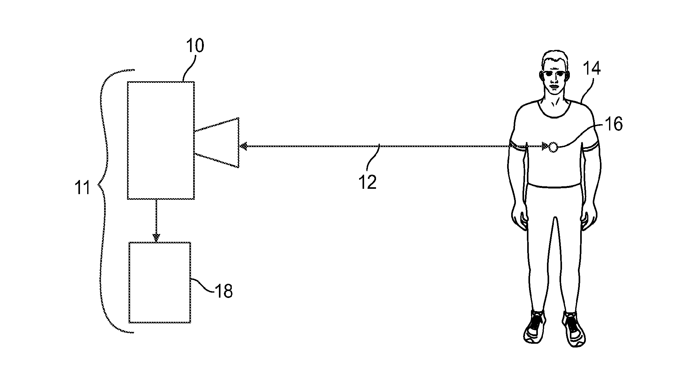
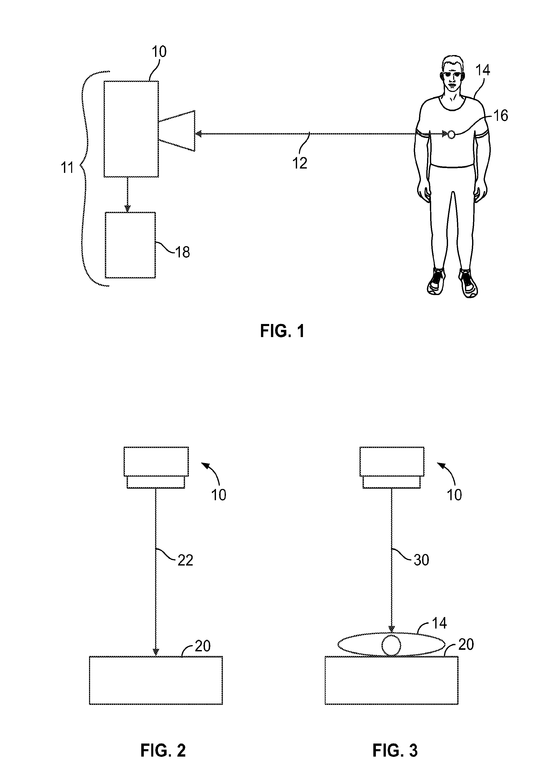
[0046]FIG. 1 is a schematic illustration of an embodiment of a sensing system 11. In one or more embodiments of the inventive subject matter described herein, the sensing system includes a high-resolution distance sensing assembly 10 (also referred to as a sensor) is used to measure a distance 12 to one or more targets 14, and / or the position of the target or targets. The target can include a living being, such as a human or other animal. A specific target location 16 may be any physical point of the body, tissue interface, or other transition in material of the target, such as the front of the chest, the hand, or any part of the body of the target, any surface of the body, an internal structure of the body of the target (such as the heart or lungs), or the like. The target location may be less than the entirety of the target, and may be a relatively small location, such as a single point, line, or the like. The target location represents the part of the target from which the distan...


PUM


Abstract

A sensing system (11) includes a first radar sensing assembly (10; 3104, 3106; 4100, 4200) and an analysis system (18). The first radar sensing assembly (10; 3104, 3106; 4100, 4200) measures plural distances (12; 22, 30; 42, 50, 60, 70, 80; 4102, 4202) to a first target location (16) at different times using radar. The analysis system (18) receives the plural distances (12; 22, 30; 42, 50, 60, 70, 80; 4102, 4202) from the first radar sensing assembly (10; 3104, 3106; 4100, 4200) and quantifies movements of a target object (14) at the first target location (16) at the different times by calculating differences in the plural distances (10; 3104, 3106; 4100, 4200) measured by the first radar sensing assembly (10; 3104, 3106; 4100, 4200). The analysis system (18) generates one or more first quantified activity level values indicative of the movements of the target object (14) at the first target location (16) using the differences in the plural distances (12; 22, 30; 42, 50, 60, 70, 80; 4102, 4202) that are calculated.

Description

CROSS-REFERENCE TO RELATED APPLICATIONS[0001]This application is a national stage entry of, and claims priority to, International Application No. PCT / US2013 / 063253, having an international filing date of 3 Oct. 2013, which claims priority to U.S. Provisional Application Ser. No. 61 / 710,397, filed 5 Oct. 2012, and titled “High Resolution Distance Sensing And Its Applications And Systems,” the entire disclosures of which are incorporated by reference.TECHNICAL FIELD[0002]One or more embodiments described herein relate to non-contact, non-invasive sensing of vital signs or other health signals using radar or other high-resolution distance sensing.BACKGROUND[0003]Known radar systems transmit analog electromagnetic waves toward targets and receive echoes of the waves that reflect off the targets. Based on the distance between antennas that transmit the analog waves and the target objects, and / or movement of the target objects, the strength and / or frequency of the received echoes may chan...

Claims


Application Information

Patent Timeline
IPC IPC(8): A61B5/11G01S13/50G01S13/87A61B5/00A61B5/113A61B5/0205A61B5/1455G01S13/88G01S7/41
CPCA61B5/1128A61B2576/00G01S13/50G01S13/87G01S7/415A61B5/1118A61B5/1117A61B5/113A61B5/0205A61B5/14552A61B5/0035A61B5/7278A61B5/7246A61B5/1114A61B5/05A61B5/0816A61B5/024A61B2562/0233G01S13/88A61B5/0507G01S13/325A61B5/11A61B5/1112A61B5/02416A61B5/1135A61B5/14551G01S7/358
Inventor AL-ALUSI, SAYF
Owner TRANSROBOTICS INC
Learn More