Gas turbine engine with distributed fans

a technology of distributed fans and turbine engines, which is applied in combination engines, machines/engines, mechanical devices, etc., can solve the problem of limited ability to increase, and achieve the effect of the highest gear reduction ratio

Active Publication Date: 2015-08-13
RTX CORP
View PDF5 Cites 11 Cited by
  • Summary
  • Abstract
  • Description
  • Claims
  • Application Information

AI Technical Summary

Benefits of technology

[0018]In another embodiment according to any of the previous embodiments, a highest gear reduction ratio is provided on the largest diameter fan rotor.

Problems solved by technology

However, the ability to make this increase is somewhat limited by the packaging envelope available on an aircraft.
However, the proposals for driving the plurality of fan rotors have deficiencies in general.

Method used


Image

  • Gas turbine engine with distributed fans
  • Gas turbine engine with distributed fans
  • Gas turbine engine with distributed fans

Examples


Embodiment Construction

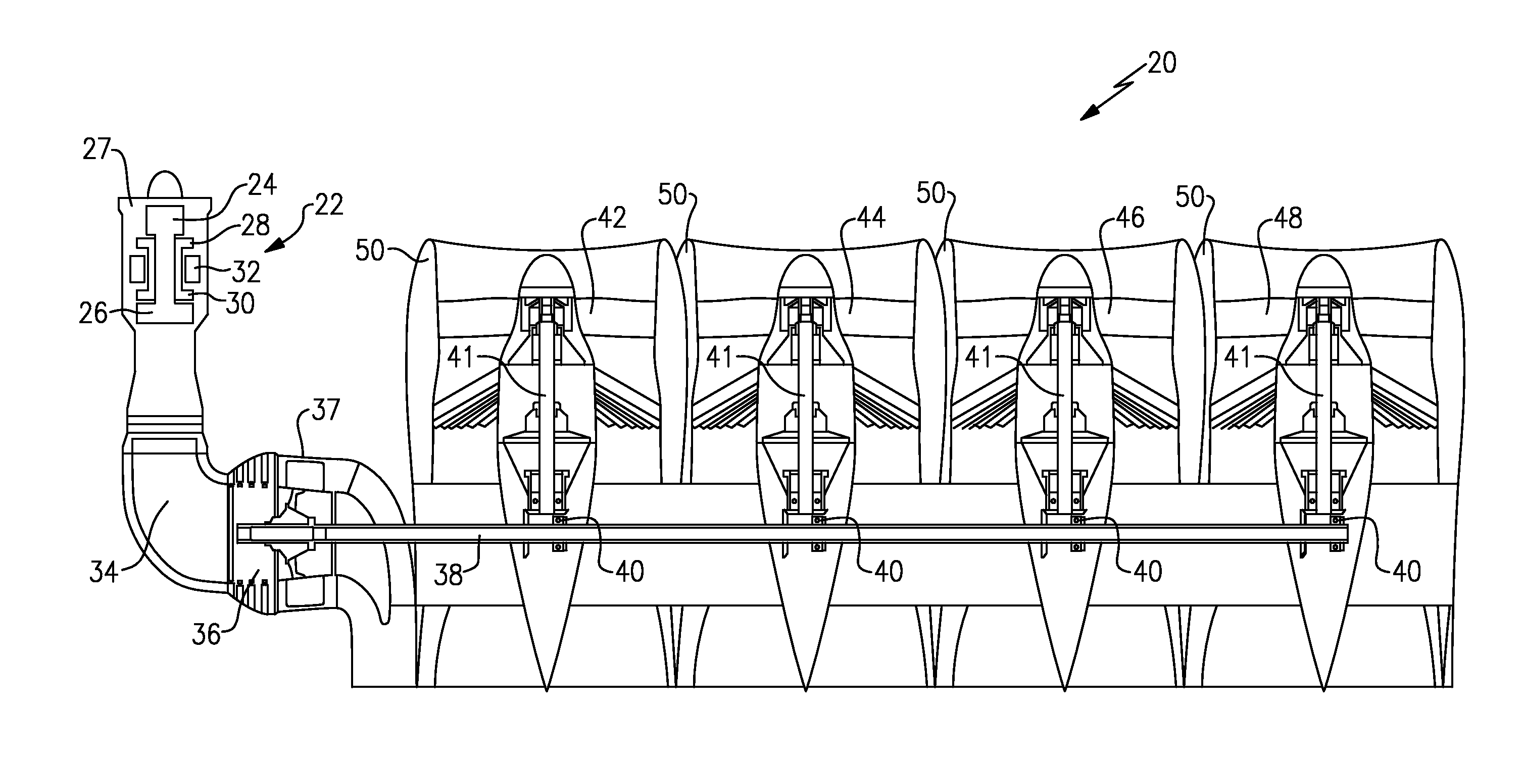
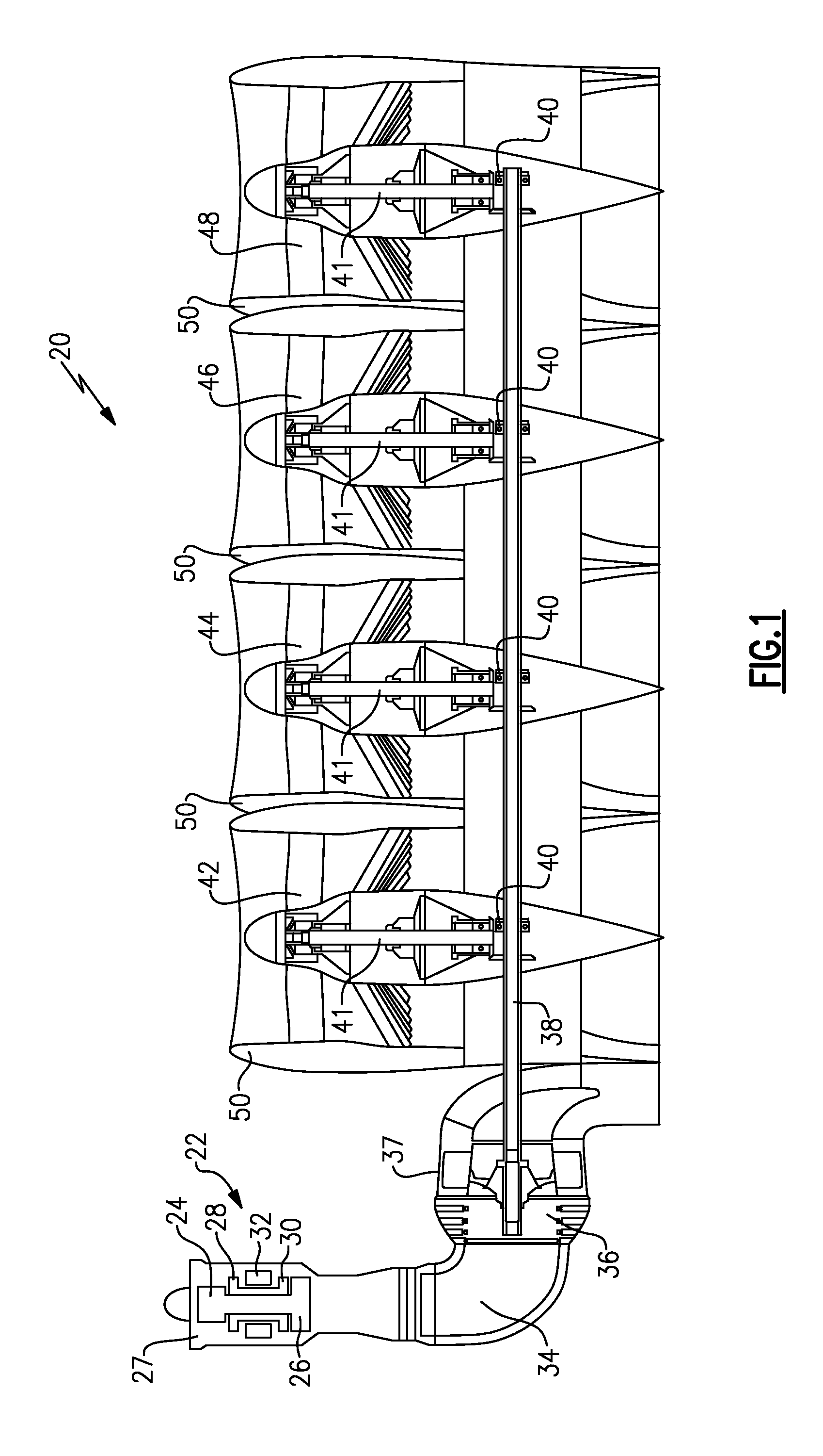
[0034]A gas turbine engine 20 is illustrated in FIG. 1 having a gas generator 22. The gas generator 22 may be a two spool gas generator having a low speed spool in which a first upstream compressor rotor 24 driven by a downstream or low pressure turbine rotor 26. A high speed spool includes a high pressure compressor rotor 28 rotating with a high pressure or upstream turbine rotor 30. A combustion section 32 is positioned intermediate rotors 28 and 30.

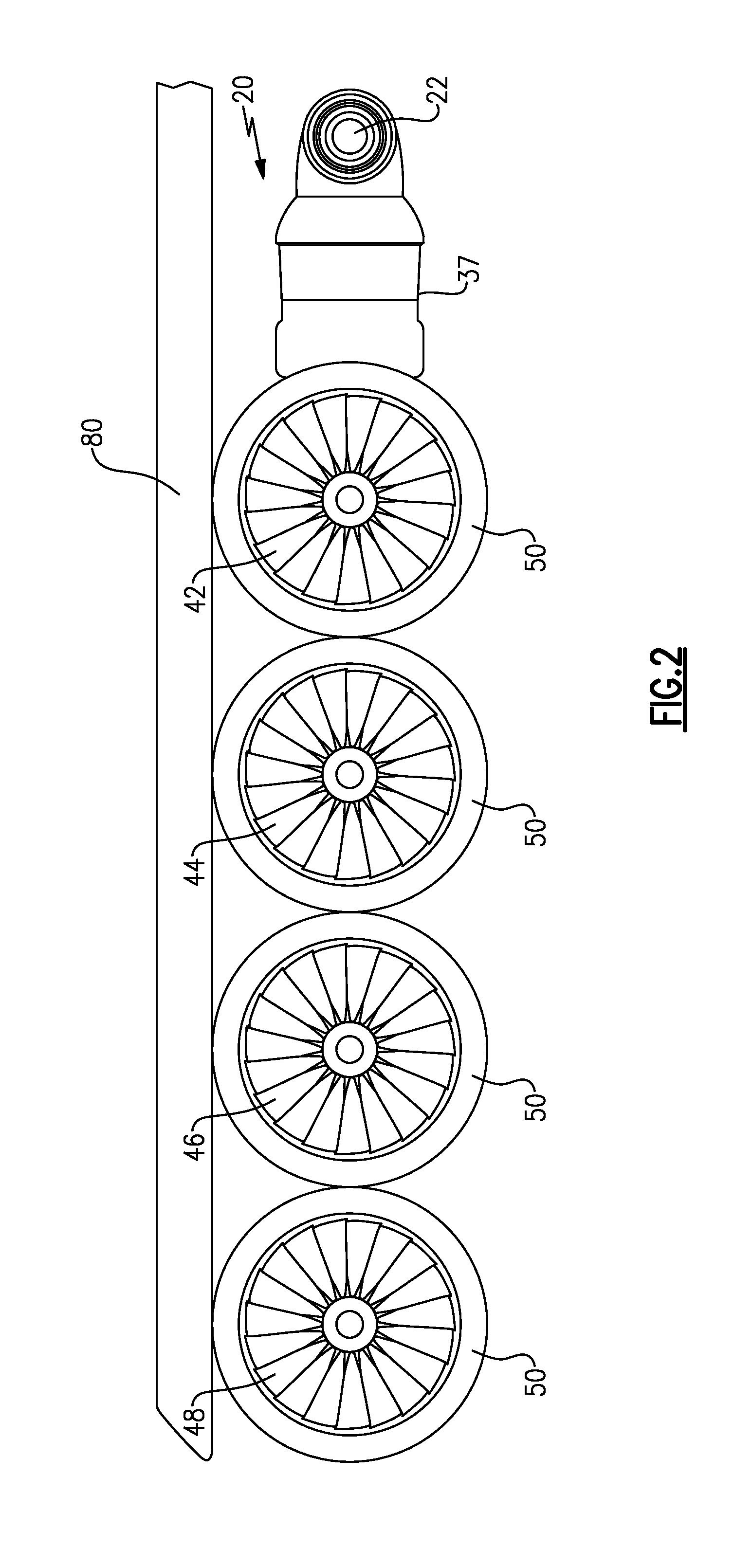
[0035]An exhaust duct 34 is positioned downstream of the gas generator 22 and receives products of combustion which have driven the turbine rotor 26 to rotate. These products of combustion pass across a fan drive turbine 36 mounted in a housing 37. The fan drive turbine 36 drives a shaft 38 that engages a plurality of bevel gears 40 to, in turn, drive shafts 41 associated with fan rotors 42, 44, 46 and 48. Each of the fan rotors 42, 44, 46 and 48 are mounted within separate housings 50.

[0036]By providing a single shaft 38, which drives...


PUM


Abstract

A gas generator has at least one compressor rotor, at least one gas generator turbine rotor and a combustion section. A fan drive turbine is positioned downstream of a path of the products of combustion having passed over the at least one gas generator turbine rotor. The fan drive turbine drives a shaft and the shaft engages gears to drive at least three fan rotors.

Description

CROSS-REFERENCE TO RELATED APPLICATION[0001]This application claims priority to U.S. Provisional Patent Application Nos. 61 / 989,675, filed May 7, 2014; 61 / 938,907, filed Feb. 12, 2014; and 61 / 937,153, filed Feb. 7, 2014.BACKGROUND OF THE INVENTION[0002]Gas turbine engines are known and typically include a fan delivering air as bypass air into a bypass housing and further delivering air into a core engine. Air in the core engine is directed into a compressor where it is compressed. The compressed air is then delivered into a combustion section where it is mixed with fuel and ignited. Products of this combustion pass downstream over turbine rotors, driving them to rotate.[0003]Recently, it has been proposed to increase the diameter of the fan to, in turn, increase bypass ratios, or the volume of air delivered as bypass or propulsion air compared to the volume of air delivered into the core engine. However, the ability to make this increase is somewhat limited by the packaging envelope...

Claims


Application Information

Patent Timeline
Patent Type & Authority Applications(United States)
IPC IPC(8): F02C3/107F02C9/18F02C3/067F02C3/06
CPCF02C3/107F02C3/06F05D2220/323F02C3/067F02C9/18B64D35/04F01D13/003F02K3/077F02C7/36F05D2220/36F05D2240/40F05D2250/312B64D27/18
Inventor SUCIU, GABRIEL L.MCCUNE, MICHAEL E.CHANDLER, JESSE M.EPSTEIN, ALAN H.O'FLARITY, STEVEN M.HANLON, CHRISTOPHER J.SCHNEIDER, WILLIAM F.STAUBACH, JOSEPH B.KENYON, JAMES A.
Owner RTX CORP
Why Eureka
Try Eureka