Resonator for vehicle

a vehicle and resonance technology, applied in the field of resonances for vehicles, can solve the problems of reducing the degree of frequency tuning freedom, limiting the number of resonance chambers of the resonance, and unable to perform frequency tuning work for external air over a broad band, so as to reduce the noise of the intake, increase the number of resonance chambers, and reduce the effect of intake nois

Active Publication Date: 2015-08-13
COOPER STANDARD AUTOMOTIVE & IND INC
View PDF17 Cites 10 Cited by
  • Summary
  • Abstract
  • Description
  • Claims
  • Application Information

AI Technical Summary

Benefits of technology

[0010]The present disclosure is directed to providing a resonator for a vehicle, which may enhance the degree of frequency tuning freedom for air introduced into a resonance chamber by forming a plurality of resonance chambers between an outer pipe and an inner pipe of the resonator.
[0011]In one aspect, there is provided a resonator for a vehicle, which reduces intake noise by using a resonance chamber for frequency tuning, the resonator including: an outer pipe having a first outer pipe with an inlet for introducing external air and a second outer pipe with an outlet for discharging the air introduced into the inlet to outside; an inner pipe disposed inside the outer pipe and having a plurality of slits for giving a passage of air; and an expansion pipe inserted between the outer pipe and the inner pipe to partition a space between the outer pipe and the inner pipe into a plurality of spaces and thus partition the resonance chamber into a plurality of regions.
[0012]According to the present disclosure, since an expansion pipe is inserted between an outer pipe and an inner pipe, the number of resonance chambers formed between the outer pipe and the inner pipe may increase, and thus the degree of frequency tuning freedom may also be enhanced.

Problems solved by technology

The intake pulsation causes noise due to the change of air pressure, and particularly, greater noise is caused due to air resonance of a vehicle body or an indoor space of the vehicle.
However, this resonator has a limit in the number of resonance chambers, and thus the frequency tuning work for external air cannot be performed over a broad band.
In other words, since the resonator has a limited number of resonance chambers, the degree of frequency tuning freedom is low, and thus the noise reduction for external air is not performed agreeably.
However, in spite of this technique, the number of resonance chambers for noise reduction is still limited, and thus it is not easy to reduce noise of a broad band.
In particular, a turning work at a high frequency band is not easy, and thus noise reduction efficiency for external air is low.

Method used


Image

  • Resonator for vehicle
  • Resonator for vehicle
  • Resonator for vehicle

Examples


first embodiment

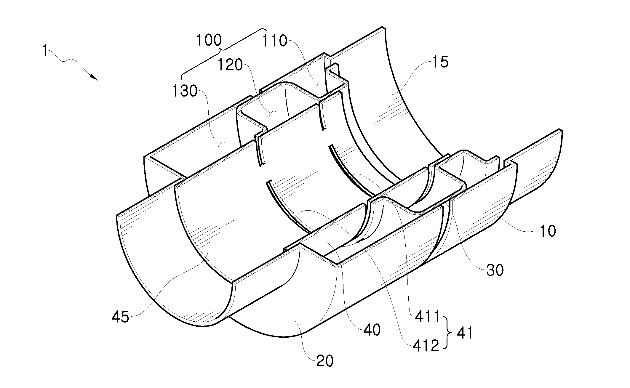
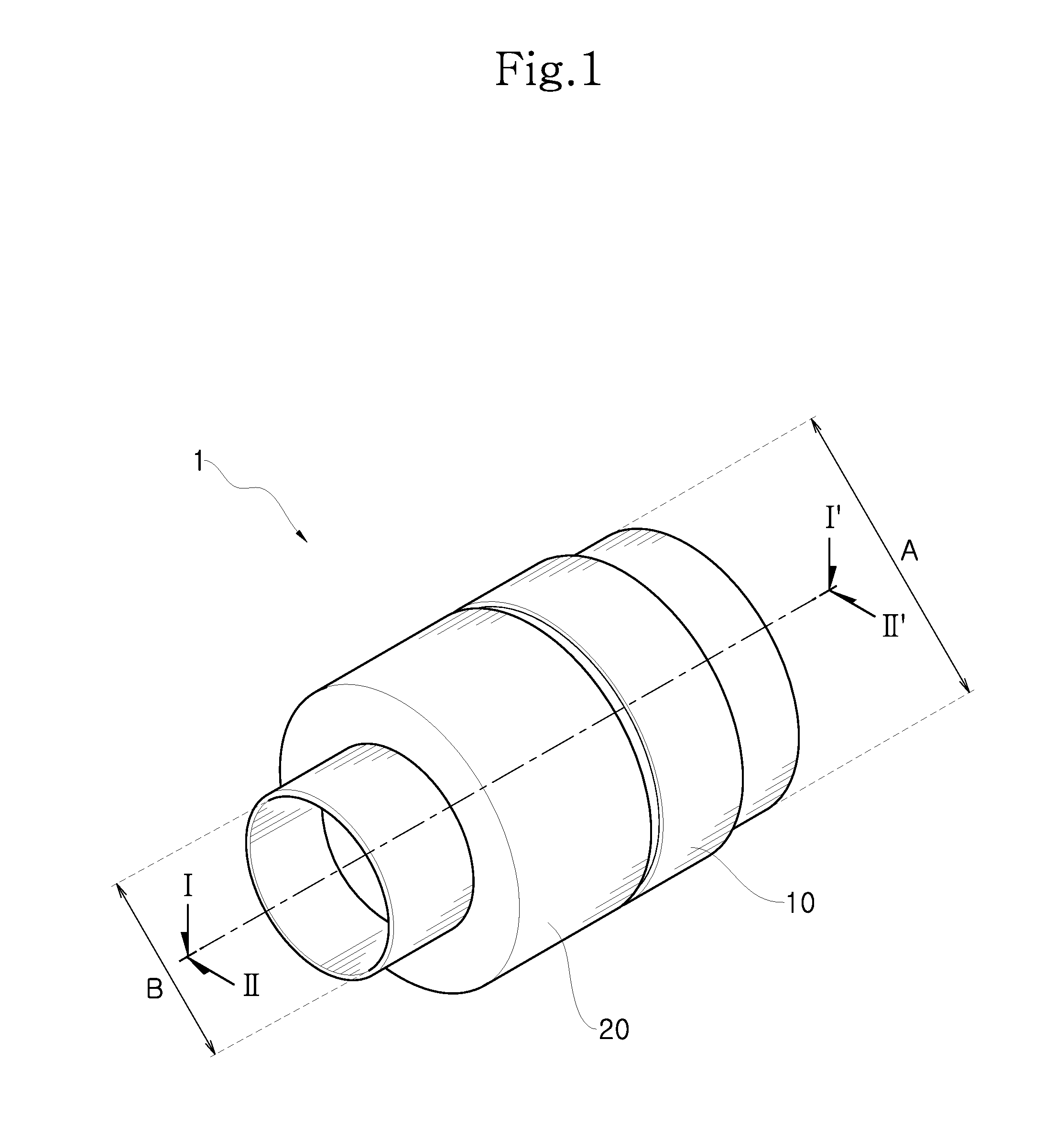
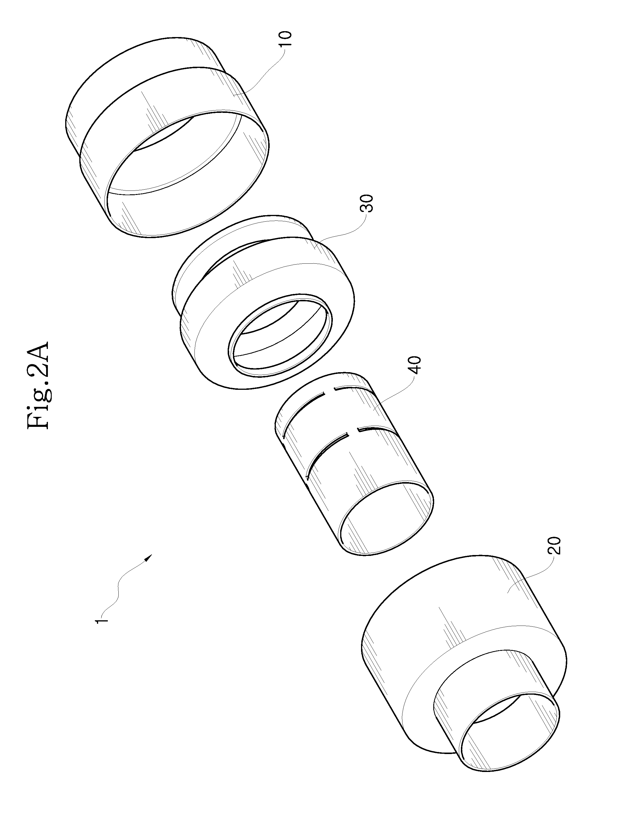
[0031]FIG. 1 is a perspective view showing a resonator according to the present disclosure, FIG. 2a is an exploded view showing a detailed configuration of the resonator, FIG. 2b is a perspective view showing an expansion pipe which is a component of the resonator, FIG. 3 is a cross-sectional view, taken along the line I-I′ of FIG. 1, and FIG. 4 is a cross-sectional view, taken along the linen-II′ of FIG. 1.

[0032]A resonator 1 according to the present disclosure includes a first outer pipe 10 configuring a part of an outward appearance and a second outer pipe 20 configuring another part of the outward appearance. An end diameter A of the first outer pipe 10 and an end diameter B of the second outer pipe 20 may be different from each other. For example, the end diameter A of the first outer pipe may be greater than the end diameter B of the second outer pipe. In addition, an end of the first outer pipe 10 may be an inlet 15 serving as an inflow passage of air, and an end of the secon...

second embodiment

[0071]FIG. 10 is an enlarged view showing the portion E of FIG. 9, in which a flow of air passing through the resonator according to the present disclosure is depicted.

[0072]As shown in FIG. 10, in the resonator 2 of this embodiment, the plurality of pipes are coupled to each other by welding. In detail, coupling (a) between the first outer pipe 10 and the second outer pipe 20, coupling (b) between the inflow expansion pipe 400 and the inner pipe 40, coupling (c, d) between the discharge expansion pipe 600 and the inner pipe 40 and coupling (e) between the second outer pipe 20 and the inner pipe 40 are all performed by welding. Since the plurality of pipes are hermetically sealed by welding, it is possible to prevent a leakage of external air and thus maximize the efficiency of intake noise reduction.

[0073]Even though it has been illustrated in this embodiment that the plurality of pipes are coupled by welding, the present disclosure is not limited thereto, and another coupling meth...

third embodiment

[0092]FIG. 13 is an enlarged view showing the portion F of FIG. 12, in which a flow of air passing through the resonator according to the present disclosure is depicted.

[0093]As shown in FIG. 13, in the resonator 3 of this embodiment, the plurality of pipes 10, 20, 40, 530 and the barriers 510, 520 are coupled to each other by welding. In detail, coupling (a) between the first outer pipe 10 and the first barrier 510, coupling (b) between the inner pipe 40 and the first barrier 510, coupling (c) between the intermediate pipe 530 and the second barrier 520 and coupling (d) between the second barrier 520 and the inner pipe 40 are all performed by welding. Since the plurality of pipes are hermetically sealed by welding, it is possible to prevent a leakage of external air and thus maximize the efficiency of intake noise reduction.

[0094]Even though it has been illustrated in this embodiment that the plurality of pipes are coupled by welding, the present disclosure is not limited thereto, ...


PUM


Abstract

A resonator for a vehicle, which reduces intake noise by using a resonance chamber for frequency tuning, includes an outer pipe having a first outer pipe with an inlet for introducing external air and a second outer pipe with an outlet for discharging the air introduced into the inlet to outside, an inner pipe disposed inside the outer pipe and having a plurality of slits for giving a passage of air, and an expansion pipe inserted between the outer pipe and the inner pipe to partition a space between the outer pipe and the inner pipe into a plurality of spaces and thus partition the resonance chamber into a plurality of regions.

Description

CROSS-REFERENCE TO RELATED APPLICATION[0001]This application claims priority to Korean Patent Application No. 10-2014-0016722 filed on Feb. 13, 2014, No. 10-2014-0016724 filed on Feb. 13, 2014 and No. 10-2014-0100471 filed on Aug. 5, 2014, and all the benefits accruing, therefrom under 35 U.S.C. §119, the contents of which in its entirety are herein incorporated by reference.BACKGROUND[0002]1. Field[0003]The present disclosure relates to a resonator for a vehicle, and more particularly, to a resonator for a vehicle, in which a plurality of resonance chambers are formed between an outer pipe configuring an outward appearance and an inner pipe disposed inside the outer pipe to improve noise reduction performance of the resonator.[0004]2. Description of the Related Art[0005]Generally, an intake system of a vehicle includes an air cleaner, a turbo-charger, an inter-cooler, an air duct and an engine manifold, and an external air introduced into an internal combustion engine by the intake...

Claims


Application Information

Patent Timeline
Patent Type & Authority Applications(United States)
IPC IPC(8): F02M35/12
CPCF02M35/1255F02M35/1036F02M35/1211F02M35/1216F02M35/1233F02M35/1266F02M35/1227
Inventor HWANG, HO JUNLEE, JUNG UK
Owner COOPER STANDARD AUTOMOTIVE & IND INC
Why Eureka
Try Eureka